E-Archive
Cover Page
in Vol. 13 - July Issue - Year 2012
Getting Ceramic Shot Benefits from Wheel-Turbine Equipment
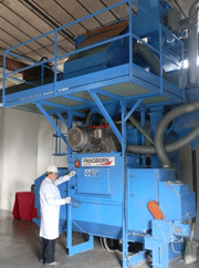
Pilot wheel turbine equipment for ceramic shot peening of automotive components
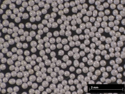
Picture 1: High grade ceramic shot (210-300

Table 1: Available ceramic shot types and sizes

Chart 1: Safe Almen intensity level according to ceramic shot type and size

Figure 1: Ceramic shot behavior
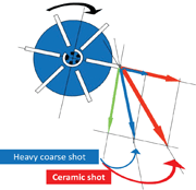
Figure 2: Velocities composition using steel or ceramic shot

Figure 3: Control cage positions when using steel or ceramic shot
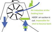
Figure 4: Avoiding crushing by back swallowing into the wheel
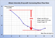
Chart 2: 30% drop of Almen intensity when increasing the mass flow rate
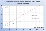
Chart 3: Amperage as a linear function of mass flow rate when using steel or ceramic shot; ceramic shot requires only 1/4th energy vs. steel shot
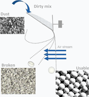
Figure 5: Air-wash separator is efficient in shape selection of light, fine and round shot from broken shot and dust
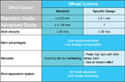
Table 2: Specific equipment design features for ceramic shot
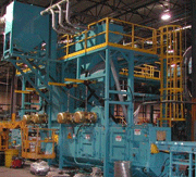
Picture 2: High output wheel turbine equipment for ceramic shot peening of suspension coil springs
Ceramic shot is recognized as bringing technical performance and cost effectiveness when using air-nozzle equipment. The purpose of this paper is to give an overview upon further ceramic use with wheel turbine equipment, drawing the same and even additional benefits.
Pangborn Europe Collaboration
Pangborn Europe has been involved in the analysis of the impact of the ceramic shot-peening process in wheel turbine equipment and collaborated with SEPR Saint-Gobain ZirPro in carrying out ceramic shot tests at its test laboratory in Caronno Pertusella – Italy (see the cover picture by courtesy of Pangborn Europe). The original wheel equipment technology has been developed to optimize the results of ceramic shot by improving the wheel technology, as well as by studying and implementing equipment new technical solutions to perform ceramic wheel shot peening in the automotive industry.
The ceramic shot
• Zirconia-based ceramic made by fusion (see picture 1).
• Shot sight: spherical shape, smooth surface, narrow size range.
• Micro Structure: monoclinic Zirconia (67%), inserted in an amorphous glassy silica phase (33%). No free silica. The very fine microstructure of ceramic shot brings a high toughness.
• Chemical properties of ceramic shot: no contamination, no fire, neither self-explosion risk.
The ceramic shot development since early 80’s
Ceramic shot was introduced in the shot-peening market in the early 80’s for manufacturing, maintenance, repair, and overhaul of aircraft structures and engine components. The technical advantages in fatigue behavior were predominant incentives. Most equipment within the aerospace industry is air-nozzle machines with strict control functionality.
Since the early 2000’s, this industry also started targeting industrial efficiency and cost-effectiveness. This is why nowadays, most of the requirement lists for ceramic shot use in aerospace industries also include compressed-air consumption savings, faster processing, versatility towards equipment and target material, elimination of post peening operations such as decontamination and polishing, closer control upon process parameters, and consistency in peening process results… All this is leading to significant cost-savings and higher productivity.
In the meantime, a basic version of ceramic shot started spreading in tool cleaning and metal finishing applications. This means that hundreds of little wheel-blast machines from different equipment manufacturers were converted with ceramic shot globally. Each of these machines is equipped with one to three wheels.
This strong experience is now capitalized, which allowed further expanding to the shot peening process with wheel turbine equipment for automotive industry.
Ceramic shot behavior
Ceramic shot does not wear and burst straight into dust, hence does not generate any dust. Ceramic shot breaks into a few pieces with a very constant rate, depending on the peening energy level (see Chart 1).
As a result, in a real machine, the workload of ceramic shot keeps as new until breaking (see Figure 1).
• Safe energy level.
In order to keep the ceramic shot within the safe Almen intensity range, it is recommended that the Almen intensity be kept below the critical level, according to the ceramic shot size and type (see Chart 1). This is made easier since the ceramic shot is efficient at a low energy level.
Key machine design and tuning points for ceramic shot use with wheel turbine
• Propelling ceramic shot throughout wheel turbines.
In the following lines, only a basic design using straight radial blades with a mechanical impeller is taken into account (see Fig. 2). Some specific wheel designs have given good results and they are the "intellectual property" of original peening equipment manufacturers, therefore will not be presented here.
For a given rpm rate, light fine ceramic shot is propelled in a different direction and with a higher resultant speed vs. heavy coarse shot (see Fig. 2).
The shot tangential velocity is the one of the blade tip. It is the same, whatever the shot type and size. Its modulus is easily calculated with the following formula:
Vt (m/s) = ? . r
Where ? (rd/s) is the angular rotation speed and r (m) is the wheel radius at blade tip.
Note: unless otherwise specified, the tangential velocity is the one given by the equipment manufacturer.
The shot radial velocity is not only dependent on simple mechanical laws but also on the dynamic shot behavior whilst travelling along the blade; friction, ricochets, flying in the air stream generated by the wheel? The modulus of shot radial velocity is easy to evaluate by measuring the shot ejection angle. Some measurements have been carried out with a wheel size of 335 mm run at 2975 rpm. The result is a 20° difference between ejection angles for steel shot S110 vs. ceramic shot of the same mean size. In this case, the modulus of the resultant ceramic shot velocity is 25% higher for the same wheel rpm.
As they are helping the air stream carrying the shot along the blades in the radial direction, the ceramic shot lightness and fineness explain this. It is then very beneficial to take this into account and possibly reduce the wheel turbine rpm.
Another consequence is that the control cage index should be adequately moved forward in order to avoid the ceramic shot blasting inside the wheel housing (see Fig. 3).
As the ceramic shot is following the air stream, an open funnel at wheel feeding will help the ceramic shot flow through the impeller. The ceramic shot being elastic, a "hoof" placed at the wheel back will avoid swallowing back and crushing the ceramic shot after ricocheting on the work part (see Figure 4).
• Optimal mass flow rate.
Wheel turbine equipment is mostly designed to propel and recycle steel shot. For a given turbine size and rpm, the maximum flow rate with steel shot is limited by the maximum acceptable amperage at the motor. Consequently, in case of over-feeding of the wheel with steel shot, the safety switch would stop the motor.
Ceramic shot being twice lighter than steel shot, before the same safety switch would cut off the electrical power to the motor, it would send twice too much bulk flow feeding the turbine and throughout the recycling system (see Chart 2). A good image of what happens then with the impeller inside the control cage is the "coffee mill". This would result in a fast ceramic shot-crushing rate, therefore generating a lot of dust with very poor blast stream efficiency. This is the reason why it is recommended to set the maximum mass flow rate with ceramic shot at half that with steel shot, but with same bulk flow rate.
This means that the ceramic shot requires only half the amperage vs. steel shot for the same bulk flow rate (impact numbers), hence only one-fourth of the energy, since the energy is the square power of the amperage (see Chart 3). Consequently, the motors and frequency drive systems will be far cheaper to buy and run.
• Continuous ceramic shot recycling.
When the flow is kept within the adequate range, then the air-wash separator and recovery system can optimally handle the bulk flow. This will make it possible to remove the few broken shot pieces before they turn to dust (see Figure 5).
Two reasons for the broken shot being easily deflected in the air stream:
1. The fragments have at least a mass divided by 2,
2. The fragments show a flat face to the air stream, which makes like a kick happening when crossing the air stream.
Safer work of the air-wash separator can be obtained by sieving the weak broken shot flow, in order to recover the few usable shot that will be brought back into the ceramic shot hopper.
• Controlling the mass flow rate when using a wheel turbine.
Ceramic shot being non-magnetic, a specific device should be used to meter the shot flow rate. Nevertheless, the wheel amperage which is a linear function of the mass flow rate (see Chart 3) can be used to open and close the wheel feeding valve according to the real flow that should be previously calibrated.
• Wheel turbine equipment lifetime using ceramic shot.
Thanks to its lightness, fineness, smooth surface and low dust emission, the ceramic shot generates very low abrasion of the wheel turbine machines and tooling. When combined with the high ceramic shot efficiency at very low energy levels, then the equipment lifetime can be enhanced by 10 times vs. that of heavy shot.
Recommendations for ceramic shot use with wheel turbine equipment
As previously described, in most of the cases, a standard design equipment works with ceramic shot, always with the main advantages in low energy consumption and low equipment and tooling wear.
Finer ceramic shot can be advantageously used with a specific wheel design (see Table 2).
The ceramic shot recycling device and air circulation in the machine should always receive specific attention.
Application example: Shot peening of car suspension coil springs (Presented at ICSP-10 in Tokyo, 2008)
• Double peening operation
1st pass with coarse steel cut wire shot using high Almen intensity,
2nd pass with very fine standard ceramic shot grade using low Almen intensity.
• Equipment
Large multi-turbine machines each with a high output (see Picture 2).
• Benefits
High fatigue life improvements,
Possibility to remove significant amount of mass out of the springs,
Significant energy and maintenance running cost reductions.
For Information:
SEPR - Saint-Gobain ZirPro
BP 60025 - 2539 Route de Sorgues
84131 Le Pontet Cedex, France
Tel. +33.490.32.70.00
Fax +33.490.32.70.61
E-mail: zirpro@saint-gobain.com
www.zirpro.com


