E-Archive
Science Update
in Vol. 15 - July Issue - Year 2014
Evaluation of Crack Initiation and Propagation of Stainless Steel Treated by Cavitating Peening Using a Load-Controlled Plate-Bending Fatigue Tester
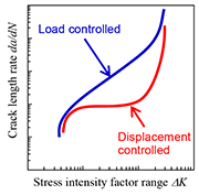
Fig. 1 Schematic diagram of the difference between load- and displacement-controlled fatigue tester
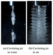
Fig. 2 Aspects of cavitating jet
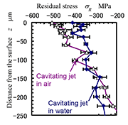
Fig. 3 Introduction of compressive residual stress into stainless steel SUS316L by cavitating jet in air and water
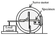
Fig. 4 Schematic diagram of load-controlled plate-bending fatigue tester
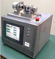
Fig. 5 Photograph of load-controlled plate-bending fatigue tester

Fig. 6 Schematic diagram of plate specimen with notch
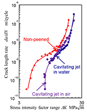
Fig. 7 da/dn
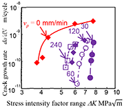
Fig. 8 da/dn
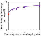
Fig. 9 ∆Kth changing with processing time per unit length
Introduction
In order to investigate the mechanism of improvement of fatigue strength of metallic materials modified by mechanical surface treatment such as cavitation peening [1-3], shot peening and laser peening, evaluation of crack initiation and crack propagation is very important. Although an evaluation method has already been standardized in ASTM [4], the target materials of the standard method are bulk materials, and it is difficult to evaluate surface-modified layers treated by peening, as thickness of the layer is normally too thin compared with the bulk material itself.
It has already been shown that a plate-bending fatigue test with a notched specimen can be useful to evaluate crack propagation of a surface-modified layer [5], and the suppression of the hydrogen embrittlement cracking of stainless steel by cavitation peening has also been demonstrated [6]. Unfortunately, most plate-bending fatigue testers on the market are "displacement controlled testers", since the mechanism of the tester is very simple. In the case of the displacement-controlled plate-bending fatigue tester, the applied load is decreased with the increase of number of cycles, as the crack grows with the number of cycles. Namely, the displacement-controlled fatigue tester cannot be used for evaluation of the crack initiation and propagation, as the stress ratio should be constant at the test (see Fig. 1). A load-controlled plate-bending fatigue tester has been developed by the authors, and now it is marketed from Tokyo Koki Co. Ltd.
In this paper, the improvement of crack initiation and propagation by cavitation peening was demonstrated using a load-controlled plate-bending fatigue tester. The used test material was stainless steel Japanese Industrial Standards JIS SUS316L.
Cavitation Peening
Cavitation normally causes severe damage in hydraulic machinery such as pumps and valves, as severe impacts are produced ast a cavitation bubble collapses. However, the impacts can be utilized to mechanical surface treatment in theas same way as shot peening. A peening method using cavitation impacts is called as "cavitation shotless peening" [1] as shots are not required, or simply called "cavitation peening" [6]. Cavitation peening can introduce compressive residual stress [7] and improve fatigue strength [1].
Normally, cavitation iswas generated by injecting a high- speed water jet into a water- filled chamber, i.e. a cavitating jet in water. Soyama realized a cavitating jet in air by injecting a high- speed water jet into a low- speed water jet, which was then injected into air, using a concentric nozzle (see Fig. 2) [8-10]. The cavitating jet in air can introduce high compressive residual stress into the sub-surface and the cavitating jet in water can introduce compressive residual stress in deeper regions (see Fig. 3) [11]. Namely, the cavitating jet in air corresponds to shot peening using small shots at high speed, and the cavitating jet in water corresponds to shot peening with large shots at low speed. The cavitating jet in air is very useful to apply cavitation peening to practical applications. For example, it can be used for mitigating stress corrosion cracking arisingen in outer surfaces of tanks and pipes of chemical plants, which cannot be put in a water- filled chamber.
In order to use cavitation peeing to applications, the enhancement of aggressive intensity of the cavitating jet is necessarily to improve peening effect and/or to shorten processing time. Soyama successfully enhanced the aggressive intensity of the cavitating jet by considering outlet bore, cavitator, and guide pipe, which were set to the nozzle for the cavitating jet [12, 13].
In the case of cavitation peening, as impacts produced by shock wave at cavitation bubble collapses are used, the optimum injection pressure of the high- speed water jet is comparatively low such as 10 ¡V 30 MPa [14] compareding with the pressure of the jet at water jet peening, in which the impacts induced by the collisions of water droplets were used [15]. This means that initial and running costs of cavitation peening areis inexpensive.
Load Controlled Plate Bending Fatigue Tester
Figure 4 illustrates the schematic diagram of a load-controlled plate-bending fatigue tester and Fig. 5 shows the photograph of the tester. In the experiment, a plate specimen with a notch as shown in Fig. 6 was used. The notch was introduced by a milling machine. The notch was introduced after cavitation peening to avoid the deformation of the notch by the impacts at cavitation peening. The details of the load-controlled fatigue tester are in the references [16].
In order to obtain the relation between crack growth rate da/dn and stress intensity factor range ∆K, i.e., da/dn ¡V ∆K diagram, crack propagation was investigated using the plate-bending fatigue tester. The applied load £m£\ a was calculated by the following equation.
"formula can not be displayed online" (1)
Here, M, W and t are bending moment, width and thickness of the specimen. Stress intensity factor range ∆K was obtained by using Newman-Raju Equation [17] as follows.
"formula can not be displayed online" (2)
Here, b and ∆£m£\ are crack depth and 2 £m£\. J, , S and H are shape factors. As the crack propagated three dimensionally, b was estimated by the crack length on the surface during the fatigue test using the following equation.
"formula can not be displayed online" (3)
Equation (3) was the experimental formula obtained by observing the cross-sectional shape of broken specimen after the fatigue test at the certain number of cycles.
In order to investigate threshold stress intensity factor range ∆Kth, K-decreasing crack growth test was carried out. As ∆Kth depends on the decreasing rate, the load was decreased gradually. The ∆Kth was defined as ∆Kth at da/dn = 10-10 m/cycle.
Reduction of Crack Growth Rate by Cavitation Peening
Figure 7 illustrates da/dn ¡V ∆K diagram for non-peened specimen and cavitation-peened specimens treated by the cavitating jet in air and water. In the case of the cavitating jet in air, the injection pressure of the high-speed water jet was 20 MPa using a 1 mm nozzle in diameter, and the injection pressure of the low-speed water jet was 0.05 MPa using 20 mm nozzle in diameter, and the processing speed was 30 mm/min. In the case of the cavitating jet in water, the injection pressure of the high-speed water jet was 30 MPa using a 2 mm nozzle in diameter, and the scanning speed was 5 mm/min. Paris law was revealed for all cases, as the straight line was illustrated in Log-Log scale diagram around da/dn = 10-9 ¡V 10-8 m/cycle. In the case of the cavitation-peened specimen, the diagram of the non-peened specimen shifted to the right-hand side. Namely, cavitation peening can reduce crack growth rate obviously. For example, da/dn of the non-peed specimen at ∆K= 12.8 was 5.8 ¡Ñ 10-9 m/cycle. On the other hand, da/dn at ∆K = 13.2 of the cavitation-peened specimen treated by the cavitating jet in air was 3.7 ¡Ñ 10-9 m/cycle. Thus, it can be concluded that the crack growth rate around became about 64% by cavitation peening.
Improvement Threshold Stress Intensity Factor Range by Cavitation Peening
As shown in Fig. 7, the crack initiation would be delayed by cavitation peening, as ∆K of the cavitation-peened specimen at 10-10 m/cycle is larger than that of the non-peened specimen. In order to the investigate effect of cavitation peening on ∆Kth, Fig. 8 reveals da/dn ¡V ∆K diagram obtained by K-decreasing test. In Fig. 8, the specimens were treated by the cavitating jet in air at the above-mentioned condition; the processing speed vp was changed from 0 to 240 mm/s. The vp = 0 mm/s means non-peened specimen. When the processing speed was decreased, ∆K at da/dn = 10-10 m/cycle, i.e., ∆Kth was increased.
Figure 9 illustrates ∆Kth as a function of processing time per unit length tp, which was defined by the inverse of the processing speed. The ∆Kth was obtained from ∆K at da/dn = 10-10 m/cycle of Fig. 8. The ∆Kth of non-peened specimen was 3.75 and ∆Kth of cavitation-peened specimen at tp = 0.25, 0.5, 1, 2 s/mm were 5.43, 5.77, 6.43 and 7.35 respectively. It can be concluded that cavitation peening using the cavitating jet in air improved threshold stress intensity factor range within a short processing time.
Conclusions
In order to investigate the crack initiation and crack growth of the cavitation-peened layer, the load-controlled plate-bending fatigue tester was developed and the da/dn ¡V ∆K diagram was obtained by using the tester for non-peened and cavitation-peened specimen. It was revealed that the cavitation peening improved the threshold stress intensity factor range ∆Kth and reduced crack growth rate. The developed load-controlled plate-bending fatigue tester with a notched specimen is useful to evaluate the crack initiation and propagation in surface-modified layers by mechanical surface treatment such as shot peening and laser peening.
Acknowledgement
This work was partly supported by JSPS KAKENHI Grant Number 24360040. The author thanks Mr. M. Mikami, technician, Tohoku University for his help with the experiment.
References
[1] H. Soyama, K. Saito, and M. Saka, "Improvement of Fatigue Strength of Aluminum Alloy by Cavitation Shotless Peening," Journal of Engineering Materials and Technology, Vol. 124, No. 2, pp. 135-139, 2002.
[2] H. Soyama, "Improvement of Fatigue Strength by Using Cavitating Jets in Air and Water," Journal of Materials Science, Vol. 42, No. 16, pp. 6638-6641, 2007.
[3] H. Soyama, and Y. Sekine, "Sustainable Surface Modification Using Cavitation Impact for Enhancing Fatigue Strength Demonstrated by a Power Circulating-Type Gear Tester," International Journal of Sustainable Engineering, Vol. 3, No. 1, pp. 25-32, 2010.
[4] ASTM E647-13, "Standard Test Method for Measurement of Fatigue Crack Growth Rates ", ASTM International, 2013, pp. 1-48.
[5] O. Takakuwa, M. Nishikawa, and H. Soyama, "Suppression of Fatigue Crack Growth in Austenite Stainless Steel by Cavitation Peening," Key Engineering Materials, Vols. 452-453, pp. 641-644, 2011.
[6] O. Takakuwa, and H. Soyama, "Suppression of Hydrogen-Assisted Fatigue Crack Growth in Austenitic Stainless Steel by Cavitation Peening," International Journal of Hydrogen Energy, Vol. 37, No. 6, pp. 5268-5276, 2012.
[7] H. Soyama, J. D. Park, and M. Saka, "Use of Cavitating Jet for Introducing Compressive Residual Stress," Journal of Manufacturing Science and Engineering, Vol. 122, No. 1, pp. 83-89, 2000.
[8] H. Soyama, "Introduction of Compressive Residual Stress Using a Cavitating Jet in Air," Journal of Engineering Materials and Technology, Vol. 126, No. 1, pp. 123-128, 2004.
[9] H. Soyama, "High-Speed Observation of a Cavitating Jet in Air," Journal of Fluids Engineering, Vol. 127, No. 6, pp. 1095-1108, 2005.
[10] H. Soyama, T. Kikuchi, M. Nishikawa and O. Takakuwa, "Introduction of Compressive Residual Stress into Stainless Steel by Employing a Cavitating Jet in Air," Surface and Coatings Technology, Vol. 205, No. 10, pp. 3167-3174, 2011.
[11] H. Soyama, K. Nishizawa, and M. Mikami, "Comparison of Abilities of Various Cavitating Jets," Proceedings of 9th Pacific Rim International Conference on Water Jetting Technology, pp. 133-137, 2009.
[12] H. Soyama, "Enhancing the Aggressive Intensity of a Cavitating Jet by Means of the Nozzle Outlet Geometry," Journal of Fluids Engineering, Vol. 133, No. 10, pp. 101301-1-11, 2011.
[13] H. Soyama, "Enhancing the Aggressive Intensity of a Cavitating Jet by Introducing a Cavitator and a Guide Pipe," Journal of Fluid Science and Technology, Vol. 9, No. 1, pp. 1-12, 2014.
[14] H. Soyama, K. Nagasaka, O. Takakuwa and A. Naito, "Optimum Injection Pressure of a Cavitating Jet for Introducing Compressive Residual Stress into Stainless Steel," Journal of Power and Energy Systems, Vol. 6, No. 2, pp. 63-75, 2012.
[15] A. Chillman, M. Ramulu, and M. Hashish, "Waterjet Peening and Surface Preparation at 600 MPa: A Preliminary Experimental Study," Journal of Fluids Engineering, Vol. 129, No. 4, pp. 485-490, 2007.
[16] O. Takakuwa, K. Sanada, and H. Soyama, "Evaluation of Fatigue Crack Propagation in Surface Modification Layer by a Load-Controlled Plate Bending Fatigue Tester," Transactions of the JSME, Vol. 80A, No. 810, pp. smm0022-1-17, 2014.
[17] I. S. Raju, and J. C. Newman, "Stress-Intensity Factors for a Wide Range of Semi-Elliptical Surface Cracks in Finite-Thickness Plates," Engineering Fracture Mechanics, Vol. 11, No. 4, pp. 817-829, 1979.
For Information:
Department of Nanomechanics, Tohoku University
6-6-01 Aoba, Aramaki, Aoba-ku, Sendai
980-8579, Japan
E-mail: soyama@mm.mech.tohoku.ac.jp


