


E-Archive
Articles
in Vol. 1 - December Issue - Year 2000
Development of Peening/Blasting Nozzles by Layer Stripping Method
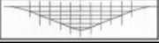
Fig. 4 Intensity Distribution of a Straight Nozzle, Injector Type, 90
Introduction: To obtain the effect called peening or abrasive blasting , solid particles such us shot or grit have to be accelerated, finally to hit the surface that requires such a treatment. An acceleration can be done in many ways. Quite common is the use of pressurized air or by a rotor with flaps. Simple as it might appear, physically it is quite complex. It needs quite an effort to get knowledge about individual particle speed, direction, spin and distribution within the collective. Not to mention what's going on after rebounding. But in practice, for the application engineer, what's important is the energetic effect on the surface to be treated.
Energetic transformation and distribution on the surface: Each particle that hits the surface will abrase or impact depending on its shape and hardness. For various reasons it will not be possible to have an equal intensity distribution of such events over the totally covered area as long as the acceleration system itself does not move. Commonly known e.g. is the so called "hot spot". Here the intensity is considerably higher than in the surrounding area. This intensity distribution is even more complex if nozzles with a rectangular orifice are used or acceleration devices with any kind of deflection such as angle nozzles. The same applies to wheel systems. For research and industrial processes it is often necessary to know more about the intensity distribution.
Measuring of intensity distribution: This can be a fairly difficult job and the scientific methods are making use of LASER or other optical systems. That means, at least the particle speed can be measured and computer modeled so informative results can be obtained. A much cheaper and more practical way can be the method as described below.
The layer stripping method "LSM": This is a simple mechanical technique for workshop use without need of expensive instrumentation.
A package of abrasive sensitive sheeting has to be exposed to the shot stream. So the individual sheets will get abraded fast in the area of highest energy transformation. Even layers will get penetrated. The idea is, to set the exposure time resulting in a local full penetration of the number of sheets installed. The result is a diacartocram like a relief that clearly shows the energetic distribution within the full area of the shot stream.
Description of process
1) A package of test sheets is placed onto a solid steel plate and fixed with a specially designed frame. The sheets are 100x100 mm. A thickness of 1 mm has been found to be most practical, also a number of 5. This finally would result in a relief with maximum 5 mm in depth.
2) The device to be tested shall be placed in the same way as when used for a normal process treatment. E.g. an angular nozzle with an outlet dia of 8 mm will be set in a distance of 80 mm from the test area. In first approach, the relative position must be estimated, so that the shot stream axis will approximately hit the center of test area.
3) The process shall then be activated for a short instance, just to see whether the effect of the shot stream is at the desired point.
4) The process can then be switched on and the duration has to be experimented with. This depends on the kind of shot and pressure etc. It can be switched on and off at any time.
The test run is completed as soon as the last sheet of the package gets worn.
5) After removal of the package, it can be examined visually or worked out by transferring the relief contour on a sheet of paper. Each layer contour represents a certain level of intensity and can be named e.g. in "%" of the maximum depth. So the distribution of intensity is clearly defined.
A typical application:
For the design and optimization of a lance for internal peening, the LSM can be an excellent tool. A nozzle for this task normally exists out of a concentric inlet, a tube according to the length required, with a cylindrical, conical or stepped reduced bore, and finally with a single or even multiple outlet under a specific angle. So 6 to 10 geometrical parameters will decide the efficiency and characteristic of the device. Under observation of the suggested standard, the LSM will first of all tell about the position of the center of the hot spot relative to the outlet position. Secondly the LSM gives the exact details of intensity distribution on to a plane surface at a certain distance from the nozzle axis center.
Range of application:
The described technique has been created specially for testing air operated straight blasting nozzles in direct pressure or injection application, but also it is very helpful on angular equipment. It simplifies evaluations of characteristics of lances used in hole peening. Also for wheel application, mainly for small units, the LSM can be quite helpful.
Limitations:
The technique described herewith informs about the energetic distribution of a plane area. The result cannot really be converted in order to represent such distributions e.g. inside a hole or any other open or closed shaped contour other then plane.
Standardization:
A guideline for a principal standardization has been worked out by the author.
I t shall help to simplify communication between research, manufacturers and processing.
Examples:
Fig. 1 shows the most simple arrangement of a straight nozzle, aimed rectangular towards the test surface.
Fig. 2 shows the distribution of a 65 mm dia wheel machine. As this is test is done with a rectangular shaped focused device, it can clearly been noticed that the main intensity is more towards the border of the bottom side and reaches 75% of the maximum even, closed to the border. This of course is a matter of the rebounding due to the focusing by the steel plates forming the outlet.
Fig. 3 shows the effect of a straight nozzle with an impact angle of 90° applied. It also could be the result of an internal lance.
Fig. 4 shows a LSM result when transformed to a graphic display.
Conclusion:
The LSM method is a most simple and inexpensive possibility to facilitate fast nozzle design or the design of similar such equipment. The so gained basic characteristic will be the base for implementation into a peening/blasting process with all the subsequent necessary settings such as pressure, mass flow and geometrical positioning.
Your contact:
R.Bosshard
ANVIL DEVELOPMENTS,
Switzerland
Tel +411 9973030
Fax +411 9973033
e-mail: anvildev@bosshard.org
Internet: www.Bosshard.org