


E-Archive
Science Update
in Vol. 18 - November Issue - Year 2017
Practical Residual Stress Measurement by X-ray Diffraction
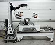
High-power open beam XRD system with a complex fixture for measuring residual stress
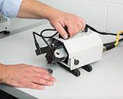
Ultraportable mXRD with full range goniometer
Introduction
The importance of residual stresses in manufactured components is receiving greater recognition with each passing year. Residual stress in metal parts can originate in forming, machining and finishing operations, in heat treatment and in the assembly of components by welding, brazing and even bolting and riveting. Their presence and magnitude may be unsuspected, or deliberate. Desirable, deliberate residual stresses can be modified by service conditions, particularly where elevated temperatures are involved, or by overhaul operations such as abrasive cleaning.
Since residual stresses are contained within parts and assemblies, the forces associated with them must be balanced within the component itself: every force has an equal and opposing force. Thus, the stresses at a point on the surface are part of a gradient whose profile is unknown. It may extend through the whole part, or be skin deep or anywhere in between.
Technically, elastic stresses and their associated strains are tensors, each made up of nine values, three orthogonal normal components and six shear components. Fortunately, in many cases, some of them reduce to near zero at the surface, including the stress perpendicular to the surface, and others are equal to each other, thus simplifying the analysis.
X-ray diffraction (XRD) provides a tool to measure the elastic strains in a thin layer close to the surface of a part. The distances between layers of atoms in crystalline materials can be measured, and changes in these distances under elastic loading can be measured with great precision. In effect, the lattice plane spacing is used as a strain gauge. With appropriate elastic constants, the stresses can be calculated, and with measurements in multiple directions, the whole tensor and the principal stresses can be determined. Details of the science of XRD, and the mathematics used to generate measurements of stress from the diffraction data can be found elsewhere.
Two basic XRD data collection techniques have been used historically for the measurement of residual stress. There are the multiple exposure type data collection techniques (known as the MET or the sin2Ψ methods which collect data over a wide range of tilts), and there are the limited tilt range type data collection techniques (known as the SET, DET, Cosα, and others). The limited tilt range techniques are very fast but are restricted to measurements of the normal stress components, rely upon very few data points to establish the slope of a line, and are not recommended for general use in the most recent US and European standard test methods. The multiple exposure type data collection techniques collect a more complete set of data from several pairs of data points, allowing the calculation of both normal and shear stress components, and accommodate the real world microstructures encountered in real world materials.
In each case, the quality of the data obtained depends on the instrument itself, and on the choices made in selecting operational parameters. That selection will be driven by details of the material to be measured and limited by the options available from the instrument.
This article will focus on a topic that has not been well addressed until recently: - The nature of real materials and the impact their nature can have on the reliability of residual stress measurements.
Ideal Materials
X-ray diffraction measurements of stress on stress free samples are typically required to demonstrate proper alignment of instruments. Samples with ‘known’ stress levels are also used to monitor the health of instruments and techniques. These samples are selected, manufactured, and may be certified to provide reliable, reproducible results. They can be seen as ideal materials.
The XRD technique for residual stress measurement uses a beam of monochromatic x-rays directed at the point of interest on the specimen surface. The diffracted beams form cones around the incident beam with the highest angle diffraction cones being the most sensitive to changes in the lattice plane spacing. The directions perpendicular to the individual crystal planes from which the diffracted beams originate bisect the angle between the incident and diffracted beams, defining the direction of measurement with respect to the specimen surface. The incident beam of x-rays is absorbed within about 0.0005 inches of the surface, so the diffracting volume, the material contributing to the diffraction cone, is defined by the area illuminated by the incident beam and its depth of penetration.
In an ideal material, all possible crystal orientations are equally represented in the diffracting volume, the crystals are undistorted, and are large enough such that their size does not affect the sharpness of their individual contribution to the diffraction pattern. In other applications of XRD, the broadening of diffraction peaks can be used to measure dislocation density and crystallite size.
Real parts
Unlike test coupons designed to demonstrate the reliability or performance of an instrument, real parts typically have additional complexities that must be addressed, to obtain reliable residual stress measurement results. It is important to recognize this fact and to be aware of the issues that can arise, and possible solutions to those issues.
The first and most obvious issue may be with the shape of the component to be measured. Ideal samples are flat, real samples may be curved, and have protrusions that limit the instrument’s access to the site of the measurement. The client who designed the component usually specifies where the measurement is needed; it may be where they expect the operating stress to be highest, perhaps in a fillet radius, or at a location where the manufacturing process is likely to generate a surface that is not typical. For example, in shot peening complex shapes, it may not be possible to achieve full coverage of all areas with normal incidence. A wise manufacturer would want to know the effect of oblique impact and/or partial coverage in the area involved, especially if that area of the part was subject to locally high operational stresses.
Effects on residual stress measurements due to curvature of the surface can be minimised by appropriate choice of beam shape, and mathematical corrections can be applied if necessary.
For the residual stress measurements, it may be necessary to cut a processed part to provide access, or to process a previously modified part to allow the x-ray goniometer space to operate. Whenever parts need to be modified to perform the measurement, great care must be taken in designing the cuts and selecting cutting methods. The aim should be to minimise changes to the stresses to be measured, by not allowing stresses that are present to relax, and not introducing new stresses with an inappropriate cutting method. Changes in the overall stress field due to cutting can be monitored with conventional strain gauges, including installations near the site of future measurements. It is good practice to place cuts as far away from the measurement site as is possible. When a series of individual parts is to be measured at identical locations, the same sectioning plan should be used for all the parts, regardless of the time between measurements. Consideration may be given to performing easily accessible measurements first before cutting to create access to others.
Real Materials
Just as real parts may present practical problems in measurement, real materials present their own practical problems.
The grain size of the test material will be the result of the part’s manufacturing history. Extremely coarse grain size may be found in castings, while extremely small grain size may be found in martensitic steels and materials produced by powder metallurgy.
Coarse grain size limits the number of grains in the diffracting volume, leading to incomplete diffraction rings and increased scatter in measurement results. Increasing the diameter of a round beam will increase the diffracting volume, but at the cost of increased beam divergence, which brings its own problems. A rectangular beam, with the long axis parallel to the tilt axis has less effect on beam divergence. The diffracting volume can be increased by oscillating the incident beam’s tilt angle through a few degrees, and the specimen in its own plane, to bring crystal orientations close to the ideal orientation into the diffracting volume. Similarly, translations of the sample can be used to increase the surface area that is seen by the beam. Care must be exercised to coordinate relative movements of the beam and specimen with the duration of each exposure so that the diffracting volume contributes uniformly to the diffraction pattern.
Fine grain size contributes to broadening of the diffraction peaks. When present with distortion of the crystal lattice, as in martensitic steels, the diffraction peaks may be broadened to the extent that the desirable high angle peaks can be difficult to see without sufficient counting time. In some Titanium alloys with a hexagonal crystal structure, broadening of the diffraction peaks causes overlaps in the tails of adjacent high angle peaks, again complicating the process of locating the peaks with precision.
Plastic strain, induced by mechanical work, may also act to broaden the diffraction peaks. The degree of broadening can be used to estimate the relative amount of cold work present in the diffracting volume. This is usually done by comparison with samples that have received known amounts of deformation or by XRD line profile analysis. The diffracting volume is actually very thin. Measurements of peak broadening after the removal of successive layers by electro-polishing can be used to monitor relative cold working as a function of depth in shot peening processes along with residual stress from the same set of diffraction data. The same techniques can be used to track the decay of residual stresses and plastic strains with exposure to service conditions of loading and temperature.
In establishing the experimental parameters for depth profile measurements of residual stress or plastic strain, it is essential to use parameters that are suitable for measurements at the surface and at the full depth of the profile, sometimes necessitating an exploratory series of measurements.
Preferred orientations of grains may be developed in materials during manufacturing operations such as rolling and forging. The deformation processes cause the shape of the grains to elongate in the direction of material flow. At the same time, the orientation of the crystal structure in each grain rotates, towards a common orientation with respect to the direction of deformation. Different preferred orientations may be found in heat-treated samples of the same material. A similar condition may be found in a material that has very coarse grains at a high temperature and undergoes a transformation to fine grains of a different crystal structure during cooling. The fine structure may consist of colonies each having a well-defined angular relationship with the parent grain. The presence of preferred orientations may be revealed by intensity changes round the diffraction cone, or by unexpected variations in the intensities of the diffracted peaks. Preferred orientation effects will be more prominent if low-index planes are used for measurements, and less prominent if high-index planes with higher multiplicity factors are used. The choice of crystal planes to use is made by the selection of target material in the x-ray tube, and the availability of a diffraction peak at a high diffraction angle. The higher the diffraction angle, the more sensitive the peak position will be to the elastic strain that is present.
Anisotropy refers to variations in mechanical properties with direction within the material. In polycrystalline materials with simple (i.e. cubic) crystal structure, it is unlikely to present a significant problem provided the x-ray elastic constants used in the stress calculation have been determined for the same crystal plane. Non-cubic crystal structures are more likely to show anisotropic properties. In these materials, and in the presence of preferred orientations, the effects of anisotropy can be significant.
Choice of Instrument and Method
Residual stress measurements were once confined to specialist laboratories, often dedicated to the development of x-ray techniques, or to the characterization of parts made using a specific manufacturing process. Later, instruments were to be found in the R&D departments of engineering companies manufacturing high tech products, and in University Laboratories. Today, use of XRD as a tool to measure residual stress has extended to include Quality Assurance applications, and most recently to Quality Control, with instruments dedicated to individual machining centres. This course of development has been accelerated by increased automation of the instruments themselves and increased computing power in the analysis of the diffraction data. The use of low power x-ray sources and high count-rate detectors have contributed safety and speed to the method.
The same developments in speed and available computing power suggest that use of the multiple exposure type data collection techniques should become a preferred method, particularly because their wide range of tilt angles reveals details of real materials that are not available in the data obtained using limited tilt range type data collection techniques.
Recent developments have expanded the range of applications, but the latest instruments appear to be focussed on increasingly ideal materials and specific applications, and lack the flexibility to adapt to the full range of real parts and real materials. There will always be applications for dedicated instruments with specialised purposes, for example, to measure stresses inside holes, or deep inside pipelines, where the best techniques simply will not fit. For the majority of applications, flexibility and adaptability are essential attributes in dealing with a diverse range of materials and parts.
For Information:
Proto Manufacturing Ltd.
2175 Solar Crescent, Oldcastle,Ontario
Canada, N0R 1L0
Tel. +1.519.737.6330
Fax +1.519.737.1692
E-mail: proto@protoxrd.com
www.protoxrd.com