


E-Archive
Science Update
in Vol. 6 - November Issue - Year 2005
Crack Arrest Of Controlled Shot Peening On Fatigue Damage Of High Strength Aluminium Alloys (Part 1)

Author: Jose Solis Romero (Ph. D.) Instituto Tecnologico de Tlalnepantla
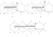
Figure 1: Schematic representation showing the effect of slip-band locked by the grain boundary on stress concentration in three stages: a) blockage of the plastic zone by the grain boundary which increases 3; b) further crack propagation until 3= c3 results into new slip-band development and c) relaxation of 3 and yielding on a new grain. The parameters 1 and 2 represent crack closure stress and cyclic yield stress respectively.
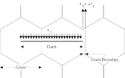
Figure 2: Schematic representation of crack arrest
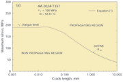
Figure 3: Predicted Kitagawa-Takahashi diagrams (a and b), plotted using Eq. (1) with 1=0 (no closure stress).

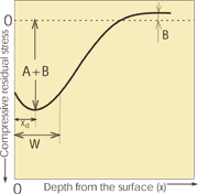
Figure 4: Schematic representation of a typical residual stress profile of a peened material, illustrating the parameters of the curve-fit equation (3).

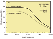
Figure 5 Comparison of the effect of the peened and unpeened crack arrest capacity of the AAs 2024-T351 (a) and 7150-T651 (b). Both curves tend to converge at long crack lengths, i.e. when the effect of the residual stress is negligible.
Introduction
Engineering surface treatments such as controlled shot peening (CSP) have been known to provide a highly effective, versatile and relatively inexpensive method for reducing damage caused by fatigue in metallic materials. This process provokes changes in the surface and subsurface layers of the target material, essentially due to the inhomogeneous plastic deformation of the surface region caused by the forces: normal to the surface (Hertzian pressure), normal and parallel to the surface (plastic stretching of the surface layer) and heat production (plastic compression of the surface). A compressive residual stress with a particular depth distribution is created simultaneously with a highly distorted subsurface layer and surface topography effects; all of them largely interrelated to the CSP parameters and material conditions [1]. In terms of fatigue damage, surface roughness will accelerate the nucleation and early propagation of cracks; strain hardening will retard the propagation of cracks by increasing the resistance to plastic deformation and the residual stress profile will provide a corresponding crack closure stress that will reduce the driving force for crack propagation.
At present, fatigue limit is considered as the maximum stress level below which an existing crack or crack-like defect will not propagate in to failure within a predetermined life span (10-100 M cycles). With the realisation that grain boundaries and other micro-structural features act as barriers to crack propagation, the Kitagawa-Takahashi threshold stress [2] has been redefined as the applied stress that is unable to overcome micro-structural barriers ahead of a crack of a given length [3] .
In the case of crack arrest, crystalline structure distortions such as grain size decreasing are considered to reinforce the fatigue resistance, while increases in surface roughness are considered to have a detrimental effect. Therefore, to better understand the effects of CSP surface modifications of fatigue damage, it is necessary to acknowledge their role in the arrest of fatigue cracks.
The Mechanics of Crack Arrest
The effect of CSP on crack arrest can be examined using the well established Navarro-Rios (NR) microstructural model [3,4]. According to the NR model, cyclic plastic deformation (crack tip plasticity) in polycrystalline materials commences and progresses in grains where the value of the critical resolved shear stress can be easily achieved. In those grains, dislocations are constrained by the stacking fault energy to remain on the original slip planes and pile-up against the grain boundary. As a result, slip-bands develop a stress concentration at the grain boundary, 3. This stress concentration (3) increases continuously with crack length until it reaches a critical value c3. At that instance, a new slip is initiated into the next grain and the concentration relaxes, Fig. 1. The process repeats itself until all the grains in the crack plane have yielded (general yielding instability). Conditions for crack arrest are met when the stress concentration at the grain boundary does not reach the level required to initiate a new slip band across the grain boundary before the crack tip reaches the grain boundary [4], as shown in Fig. 2.
In [4], it was suggested that the condition for crack arrest should follow: (1) On the Internet we can not display this complex formula. Ask MFN for the PDF version of this “Science Update”.
where, FL is the plain fatigue limit of the material at a particular stress ratio, a is the crack length, D is the average transverse grain diameter, and i is the number of half grains representing the extend of the crack and its plastic zone, i = a/(D/2). The resistance to crack opening or closure stress is represented by the parameter 1, which is dominated by the compressive residual stress. This stress is obtained by calculating the mean value between x=0 and x=a (a= crack depth) over the portion of the crack contained within the shot-peened layer.
The ratio mi/m1 is the grain orientation factor of the ith grain which for aluminium alloys was experimentally found to follow [5]: (2) On the Internet we can not display this complex formula. Ask MFN for the PDF version of this “Science Update”.
The parameter m1 in Equation (2) is related to the first grain and mi is the average factor corresponding to other successive grains. In the first grain, the orientation factor should have a value of approximately unity, since crack formation takes place in grains where the critical resolved shear stress is a maximum. It should be noted that the grain orientation factor increases monotonically with i, until fully polycrystalline behaviour is reached (Taylor’s factor mi = 3.07 for FCC metals).
Eq. (1), depicted in Fig. 3, represents a micromechanical version of the well-known Kitagawa-Takahashi diagram. In many works, Eq. (1) was considered to represent the boundary condition between a non-propagating and a catastrophic fatigue crack. The shape of the Kitagawa curve is the result of the competition between two mechanisms: (a) 1/i(0.5) , which represents the elastic stress singularity, and (b) the term mi/m1 which provides a statistical measurement of the difficult provided by high angle grains to the propagation of crack tip plasticity. It is worth noting that after a particular crack length the curve bows towards a constant gradient of -1/2 (threshold stress).
Closure Stress
Residual stress profiles can be explicitly represented by the following Gaussian function: (3) On the Internet we can not display this complex formula. Ask MFN for the PDF version of this “Science Update”.
where, R = compressive residual stress (MPa), A+B = maximum residual stress (MPa), x = depth below the surface (mm), xd = depth to maximum residual stress, W= a measure of the width of the stress curve (mm), B= preset residual stress (prestressed specimens only). A graphical description of these parameters is shown in Fig. 4.
The closure stress, i1, is obtained by calculating the mean value of the function describing the residual stress distribution between x=0 and x=a (where a is the crack depth): (4) On the Internet we can not display this complex formula. Ask MFN for the PDF version of this “Science Update”.
Predicting the Crack Arrest Capacity on the Peened Material
The physical meaning of the crack arrest capacity is twofold: a) if the length of the crack is smaller or equal to the grain size, then it symbolises the fatigue limit, denoted by the 10 million cycle mark, and b) if the length of the crack is larger than the diameter of the grain, then it defines boundary conditions of stress below which crack arrest is possible. Hence, in order to incorporate the residual stresses induced by CSP, Eq.(1) should include both the residual stress at the surface and the profile of the residual stresses as a function of crack length (depth from the surface). Therefore: (5) On the Internet we can not display this complex formula. Ask MFN for the PDF version of this “Science Update”.
The effect of SP on the crack arrest capacity over the 2024-T351 and 7150-T651 AAs can be appreciated by comparing the result of applying Eq.(1) without residual stresses and Eq.(5) containing the closure stress, as graphically shown in Fig. 5.
CONCLUSIONS
In terms of the model, fatigue limit is defined as the maximum stress level below which a crack that spans over a distance between two successive microstructural barriers (inter-barrier spacing), such as grain boundaries, will not propagate (crack arrest). Specifically, crack arrest is attained when the following two boundary conditions are present: (1) the crack tip plastic zone is completely blocked by the barrier and (2) the crack driving force is unable to initiate slip beyond that barrier [69]. Cracks can be arrested even if they are longer than one inter-barrier distance, provided the above conditions are fulfilled.
References
1. Vöhringer O. “Changes in the state of the material by shot peening”. in Shot Peening- Science-Technology-Application. Third International Conference on Shot Peening (ICSP-3). Germany: Deutsche Gesellschaft fur Metallkunde e.V. 1987.
2. Kitagawa H. and S. Takahashi. “Applicability of fracture mechanics to very small cracks or the cracks in the early stage”. in 2nd International conference on mechanical behaviour of materials (ICM2). Boston, USA.: ASM, Metal park, Ohio. 1976.
3. Navarro A. and E. R. de.los.Rios, “Compact solution for a multizone BCS crack model with bounded or unbounded end conditions”. Philosophical Magazine A., 57(1): pp. 43-50. 1988.
4. De.los.Rios E.R., “Dislocation modelling of fatigue crack growth in polycrystals”. Engineering mechanics, 5(6): pp. 363-368. 1998.
5. Curtis S., J. Solis-Romero, E. R. de.los.Rios, C. A. Rodopoulos, and A. Levers, “Predicting the interfaces between fatigue crack growth regimes in 7150-T651 aluminium alloy using the fatigue damage map”. Materials Science and Engineering A, 344: pp. 79-85. 2003.
Instituto Tecnológico de Tlalnepantla,
Tlalnepantla Edo. de Méx., 54070
México. Instituto Tecnológico y de Estudios Superiores de Monterrey (ITESM), campus Edo. de Méx., 52926, México
E-mail: solis_jose@infosel.net.mx