E-Archive
Articles
in Vol. 14 - March Issue - Year 2013
Surface Enhancement With Residual Stress
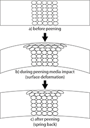
Illustration of material deformation as a result of a peening process showing: a) initial material before peening, b) surface deformation during peening media impact, and c) resultant deformation after spring back
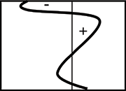
Resultant residual stress gradient with depth after peening
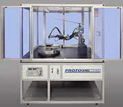
Modern x-ray diffraction system used to measure residual stress
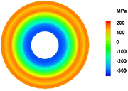
Resultant residual stresses from cold expansion of a hole
Introduction
Shot peening was first used in the 1930’s with the deliberate intention of installing residual stresses to improve the fatigue life of valve springs in automobile engines. Since then, new techniques have been developed to install residual stresses, and each imparts its own characteristics. At the same time, the application of peening processes in general has expanded to materials in critical and demanding engineering applications where the manufacturer is required to demonstrate and guarantee the reliability, safety and service life of components.
To make appropriate choices, the designer has to understand the changes that accompany the residual stresses. This article explores some of the expanding variety of processes used to introduce beneficial residual stresses, and considers some of the other changes they may bring to the component(s). It also recommends that the users of peening processes invest in the knowledge that will allow them to select the most appropriate peening techniques and parameters for their own applications.
Processes and their characteristic surfaces
Historical processes
The oldest treatment used to install compressive residual stresses in sheet metal was probably a precursor of Peen Forming, using a hammer with a convex face to create overlapping dimples on a surface. Local elastic and plastic deformation associated with each blow displaces the material under the hammer laterally, and introduces a work-hardened layer close to the surface. As the hammer leaves the surface the newly stretched layer tries to spring back toward its original position, but is restrained by the un-deformed material below the surface. The newly stretched material at the surface is left in a state of elastic compression, with the originally flat sheet formed into a curve with the hammered face on the convex side.
The compressive forces in the surface layer and the forces in the underlying material, which are tensile, are in balance. However, the surface layer is usually thin compared to the thickness of the part, so the compressive stress near the surface can be large while the reacting tensile stress below the surface is much smaller. This simple process illustrates one of the most important features of residual stress formation by local plastic deformation: Local tensile plastic deformation results in a local elastic compressive stress, and vice versa.
The compressively stressed layer corresponds closely to the material that was plastically deformed and work-hardened, so the mechanical properties of the material near the surface are also modified by the peening process. This allows the compressive residual stress near the surface to be as large as the newly elevated yield strength of the work-hardened material.
After processing, the topography of the surface depends on the shape of the tool, the force with which it is used, and the pattern of the blows, including the number of repetitions.
Modern processes
The most common current technique for installing residual stresses in surfaces is shot peening. The hammer is replaced by a stream of metal, ceramic or glass spheres, and the force of each impact is controlled by the mass and velocity of the particles. The mass of the particles is usually selected from a range of standard sizes and materials, and the correct velocity is established by measuring their effect on a series of Almen test strips used to plot "saturation curves". Details of the test procedures can be found elsewhere. Correctly used and interpreted, these tests provide an excellent system to control and monitor the intensity of peening processes in general.
A given Almen intensity may be reached using one of several combinations of media size, type and velocity. When Almen strips were first used to measure and monitor peening intensity applied to automotive valve springs, their material was chosen to be the same as the parts. However, the mechanical properties of the steel Almen strips and other materials to be shot peened will be different, so the response of the part to these different peening processes will also be different. Almen intensity alone is not enough to characterize the peened surface of a component.
Residual stress profiles may be characterised very precisely and rapidly by modern X-ray diffraction procedures, in terms of the variation of both stress and plastic deformation with depth. Traditional relaxation techniques such as blind hole drilling and sectioning strain-gauged parts can be used to evaluate larger scale residual stress fields. Micro-hardness measurements on prepared metallographic cross-sections can be used to evaluate work hardening profiles.
There are variables in practical peening processes, most notably "coverage" and "impact angle" not addressed by the Almen test.
Coverage on the part and on Almen strips are rarely the same, even when the strips are placed to simulate the position and orientation of the surface of the part. This is because the size of each dimple on the surface depends on the mechanical properties of the material being peened and on the properties of the peening media. The properties of the media can be assumed to be constant once the batch of shot has been conditioned, but the properties at the surface of the material being peened are not only different to those of the Almen strips, but are changing throughout the process. Coverage on the part needs to be established independently by inspection to determine a process duration that gives the required coverage. It is normal to accept a little less than 100% coverage because peening to achieve the final few percentage points can extend the process time unnecessarily, and even damage the surface.
Non-normal impact of shot reduces the effectiveness of the process. With oblique impact the dimples are elongated, the surface is smeared and the residual stresses take on a shear component. More importantly, the downstream lip of the dimple can be raised. Subsequent impacts can fold raised material onto the surface later as a "Peened Surface Extrusion Fold" (PSEF). Impact angle is important when complex shapes are being peened because local areas of the surface may not present the same angular relationship to the shot stream as the overall surface of the part. Features similar to PSEFs can also be formed when the peening process includes the boundaries of surfaces; impacts on these corners can lead to "Rolled Edges".
As with hammer peening, the surface topography of a shot-peened surface depends on the size and shape of the tool (the shot) and its velocity at impact. For a given Almen intensity, larger shot generates a smoother surface simply because the radius of the dimples is greater. A comparison with other metal working processes suggests that larger diameter shot will interact differently with the workpiece because of friction between the shot and the deforming surface. Friction will tend to reduce plastic flow immediately under the impacting particle, leading to a deeper zone of compressive stress, with less concentrated plastic deformation.
Some peening processes use much larger diameter contact surfaces to impact the area being treated. In Gravity Peening, large balls are allowed to fall onto the surface under treatment, and in one variety of Ultrasonic Peening, a powerful ultrasonic transducer is used to impart kinetic energy to large diameter balls contained in an enclosure with the part under treatment. In a second type of Ultrasonic Peening the transducer is used to excite captive strikers in a device which can be moved, manually or by a robot, over the surface to be treated. This device can be used to peen for residual stress, and has applications in peen forming.
An alternative to impact treatments may be found in burnishing. Burnishing can be performed by machine tools immediately after cutting, using a tool designed to both slide on and smear the surface. Smooth surfaces can be produced by burnishing, but the residual stress patterns are unpredictable. Roller burnishing is used in specific applications, for example to provide smooth surfaces, cold working and beneficial residual stresses in the fillet radii of certain bolts for critical applications, and finishing in the bores of hydraulic cylinders.
The walls of holes present particular risks for some critical components. Ballizing, an extension of burnishing, can treat the internal surfaces of holes. An oversize polished ball is forced through the drilled hole, expanding it, smearing and smoothing the wall, and installing a residual stress field of circumferential compression and axial shear. The main use of ballizing is to adjust the bore diameter, and to improve surface finish, so the residual stresses are unpredictable. In a more sophisticated approach, hole expansion, using the split sleeve technique, starts with a precisely sized hole, and places a disposable sleeve between the hole wall and a mandrel. The mandrel is pulled through the sleeve, expanding the hole without smearing the wall. The process requires access to one face of the component only, and generates repeatable residual stress patterns surrounding the hole.
Laser Shock Peening uses a high power laser pulse to initiate a shock wave in a thin coating on the surface of the part to be treated. The wave travels into the material, perpendicular to the surface. Each pulse creates a shallow depression in the surface, but there appears to be no raised material surrounding the depression as there is in peening processes that use contact with a tool, or physical impact to deform the surface. Laser Shock treatments generate deep layers of compressive residual stress with little plastic deformation at or below the surface; however, the magnitude of the residual stress may not approach the material’s compressive yield until several overlapping passes have been completed. The laser, its power supplies and ancillary equipment are physically large, so this technique currently requires that parts be brought to the machine. A significant advantage of the process is that the absence of physical tooling can allow easier access to hard-to-reach areas of components.
Conclusion: What can go wrong (and how to avoid it)
The presence of a compressive residual stress is only an advantage in service as long as it remains in the part. Several processes can modify or eliminate residual stresses. In particular, residual and service stresses are additive. If an area of a component having a local compressive stress is subjected to an additional compressive stress, local plastic deformation may occur if the compressive yield stress is exceeded. Local compressive yielding leads to a more tensile (or less compressive) residual stress! Similarly, when compressive residual stresses are reacted within the core of the component by a tensile stress, the tensile load the component can withstand may be reduced before the core yields. Even a small tensile plastic deformation of the core may result in the compressive residual stresses of the surface being eliminated and replaced by tensile residual stresses. The whole nature of the residual stress distribution and the applied stresses interact to protect the component.
Temperature excursions can reduce residual stresses by lowering the yield stress and allowing stress relief by plastic flow. Diffusion-controlled processes can also relax residual stresses over longer periods. Elevated temperatures promote stress relaxation in metals by increasing the mobility of atoms and vacant lattice sites in the metal crystals. Plastic deformation in the crystal lattice increases the initial vacancy concentration, so stress relaxation may take place faster in the presence of greater initial deformation. Not surprisingly, those processes that introduce little deformation are promoted for high temperature applications.
A compressive residual stress protects the component from fatigue cracks. If the residual stress field is compromised, stress raisers such as PSEFs and Rolled Edges can then become active fatigue origins.
Avoiding these events, or understanding them to the extent that they can be predicted and controlled, requires a detailed knowledge of each application. This can be provided by experimentation, experience, and appropriate measurements of parts in manufacturinge, test environments and service. The designer has knowledge of the part, its application, and the processes used in its manufacture. The increasing variety of surface enhancement options available to the designer requires his knowledge of their capabilities and their beneficial effects on the designed his components.
For Information:
Proto Manufacturing Ltd.
2175 Solar Crescent, Oldcastle, Ontario
Canada, N0R 1L0
Tel. +1.519.737 6330
Fax +1.519.737 1692
E-mail: robertdrake@protoxrd.com
www.protoxrd.com


