


E-Archive

Science Update
in Vol. 25 - January Issue - Year 2024
Surface Modification of Stainless Steels by Laser-Shock Peening
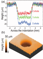
Fig. 1: LSP at a single spot on SS304 with original machining lines of ~140 µm in period and ~4 µm in peak-to-valley distance. (a) Surface height profiles across the center of the LSP-induced crater and (b) 3D mapping of the surface height, showing intact machining lines within the LSP-induced crater.

Fig. 2: LSP-induced surface craters. (a) Surface height profiles measured across the center of the LSP-induced caters on SS304L, (b) Surface height profiles measured across the center of the LSP-induced caters on SS316L, and (c) Crater depth induced by LSP on mirror-polished surface of SS304L and SS316L as a function of shot numbers.
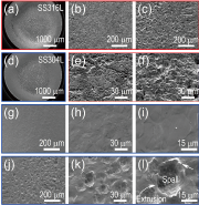
Fig. 3: Morphological modifications of mirror-polished SS304L and SS316L upon a single spot LSP for 15 shots recorded by SEM. (a) LSP crater on SS316L, (b)-(c) SS316L before LSP, (d) LSP crater on SS304L, (e)-(f) SS316L after LSP, (g)-(i) SS304L before LSP, and (j)-(l) SS304L after LSP.
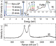
Fig. 4: Surface studies of the LSP-induced craters on mirror-polished stainless steels. (a) EDX spectra, showing the increased carbon deposition as a function of LSP shots and (b) Typical Raman spectrum, showing that the deposited carbon crystallized in graphite structures.

Fig. 5: XRD intensities obtained by probing the diffraction patterns across the center of the LSP-induced craters. (a)-(e) On SS304L and (f)-(j) On SS316L.
Introduction
Laser shock peening (LSP) is an advanced surface treatment technique developed to enhance the surface integrity of materials, primarily metals, at room temperature or below their recrystallization temperatures (i.e., cold working process) [1]. LSP works by generating controlled shockwaves on the surface of the workpiece using high-energy laser pulses. The high-energy laser pulse is focused on the surface of the workpiece, rapidly heating and vaporizing a small portion of the material. The material vaporization creates a high-pressure plasma, which generates a shockwave that travels into the material. To avoid surface damage of the workpiece during LSP, a scarification layer, e.g., black tape, is usually applied on the surface to serve as the source for generating the vapor and creating the high-pressure plasma. Furthermore, a transparent layer, e.g., lamellar water flow, is usually applied on the scarification layer to enhance the injection of the shockwave into the workpiece, leading to plastic deformation.
The shockwave, once injected into the workpiece, creates compressive residual stresses beneath the surface, which are highly beneficial for improving fatigue resistance and preventing the initiation and propagation of cracks. The intense pressure and plastic deformation induced by the shockwave also result in work hardening of the surface and near-surface regions of the workpiece, making the surface layer harder and more resistant to wear. Through plastic deformation, LSP can help close and heal surface microcracks and defects, which, along with surface hardening and compressive residual stresses, can enhance the corrosion resistance of the workpiece. The combination of LSP-induced compressive residual stresses, work hardening, and reduced surface defects significantly enhances the fatigue life of metallic components. In this light, LSP has great potential in aerospace, automotive, and other industries where improving the fatigue resistance, wear resistance, and overall longevity of critical components, especially those subjected to harsh operating conditions, is essential [2-4].
It has been proposed that LSP can offer precise control over depth and coverage, making it suitable for complex components and critical applications. The control of the treated layer can be realized by adjusting the laser energy and the number of laser pulses applied [1, 4]. However, related experimental results and their dependence on initial surface roughness are relatively scarce in literature. Additionally, it is commonly accepted that LSP does not remove material from the surface; however, much more effort is needed to understand the microscale surface modifications as well as potential contaminations, e.g., oxidation, that might be caused by the plasma during LSP. In this regard, we carried out the LSP process at a single spot on austenitic stainless steel (SS) 304L and 316L with an increased number of pulses (i.e., LSP shot numbers). The initial surface roughness and surface modifications, including morphological changes and plastic deformation-induced martensite transformation, have been discussed in terms of experimental characterizations as a function of LSP shot numbers. The obtained results can have important implications when designing and processing LSP-based cold working for surface enhancement of metallic components.
Materials and Methods
Commercial SS304L and SS316L plates measuring 50 mm × 50 mm × 2 mm were used in this study. The surfaces of the SS plates were mirror-like polished. For comparison, a 10-mm-thick SS plate with machining lines of approximately 140 µm in period and approximately 4 µm in peak-to-valley features was also employed for the LSP process. LSP was done with a laser wavelength and pulse duration of 1064 nm and 18 ns, respectively. The laser beam diameter on the surface of the workpiece was approximately 3.0 mm; the pulse energy was 10 J; and the peak power density was approximately 7.86 GW/cm². Black tape was applied to the surface of the SS plates and replaced after each LSP shot. Lamellar water flow was applied to enhance the shockwave injection into the SS plates.
Scanning electron microscopy (SEM) and a step-profilometer were employed to study the surface morphological modifications, while the LSP-induced martensite transformations and potential surface oxidations were characterized by X-ray diffraction (XRD) and micro-Raman scattering. The X-ray beam (Cu-Kα) had a 1.0 mm diameter. The excitation laser for Raman scattering had a wavelength of 532 nm and a beam diameter of 900 nm on the sample surface. Energy dispersive X-ray spectroscopy (EDX) was used to study the surface chemistry after the LSP process.
Results and Discussion
Figure 1(a) presents typical surface height profiles measured by a step-profilometer across the center of the LSP-induced craters on SS304 with original machining lines. A typical 3D mapping of the crater is shown in Fig. 1(b), where the machining lines are clearly distinguished. A comparison of the machining lines inside and outside the LSP-crater in Fig. 1 reveals that their features, i.e., the period and the peak-to-valley distance, do not exhibit any apparent changes upon the LSP process, although the crater depth and the surface waviness within the craters monotonically increase with the LSP shots. These observations suggest that the shockwave impacts the surface features evenly and simultaneously regardless of the peak or valley regions. This characteristic of LSP is significantly different from that of cold working processes based on mechanical methods such as robotic hammer peening and shot peening [5, 6], where the impact on the peaks happens earlier than on the valleys, leading to a smoother surface within the craters than outside the craters.
Figures 2(a) and 2(b) present the surface height profiles measured across the center of the LSP-induced craters on SS304L and SS316L, respectively. Their comparisons with the profiles in Fig. 1(a) confirm the increased waviness at the center of the craters as a function of the shot numbers. However, because the initial surface of the SS304L and SS316L coupons in Fig. 2 is mirror-polished, surface roughening can be seen inside the craters, especially those induced by 20 shots [see Fig. 2(b)]. Presented in Fig. 2(c) are the crater depths induced by the LSP process on smooth SS304L and SS316L as a function of shot numbers. It is noticed that the crater depth nearly linearly increased with the shot numbers, especially after 5 shots.
Figure 3 presents typical SEM images taken from the mirror-polished SS304L and SS316L coupons before and after the single-spot LSP process for 15 shots. A general observation is that surface roughening was induced by the LSP process, and the smoother the initial surface, the more significant the roughness induced by the LSP process. A careful look at the surface within the crater, e.g., in Fig. 3(l), reveals that the surface roughening is associated with extrusions induced by the ejection of materials from the surface. A further study of the LSP-processed SS samples reveals a bulge on the backside surface of the 2 mm-thick SS coupons (in Fig. 2) rather than on the 10 mm-thick SS block (in Fig. 1). This comparison, together with the extrusion-like features of the surface spallation in Figs. 3(e)-3(f) and 3(j)-3(l), suggests a combination of echoed shockwaves and the heated surface layer under the LSP process.
Chemical studies of the LSP-induced crater were then carried out by EDX and presented in Fig. 4(a). It is clearly seen that carbon was deposited on the LSP-processed surface, and the deposition increased with the number of LSP shots [see the enlarged spectra in the inset of Fig. 4(a)]. Raman scattering studies [see Fig. 4(b) for a typical Raman spectrum] reveal that the deposited carbon is crystallized in graphite structures. It is obvious that the use of black tape caused the carbon deposition through vaporization in the plasma and, therefore, deposition upon the cooling of the plasma.
Finally, XRD measurements were taken by laterally probing the diffraction patterns across the center of the LSP-induced craters. Figures 5(a) and 5(b) present the XRD intensities in the 2θ range of 39°-55°, covering the Bragg angles of γ(111), α'(110), and γ(200). A remarkable difference between SS304L and SS316L, [i.e., in Figs. 5(a)-5(e) and 5(f)-5(j), respectively] is that there is an additional diffraction peak at about 47° in SS304L but not in SS316L. In comparison, the initial α'(110) diffraction peaks were weakened at the crater edges in SS316L [see the arrows in Fig. 5(j)] but not in SS304L. The additional diffraction peak at ~47° can be assigned to ε(101) in terms of deformation-induced martensite transformations. The comparisons among Figs. 5(a)-5(e) indicate that both γ-to-ε and γ-to-α' transformations occurred in the LSP process on SS304L. However, the phase transformations are absent from the LSP process on SS316L [see Figs. 5(f)-5(j)], due to the larger stacking fault energy of SS316L than that of SS304L [1]. In contrast, the LSP-induced weakening in the XRD intensities from the initial α'-phase (remaining on the surface due to mechanical processes) as indicated by the arrows in Fig. 5(j) can be attributed to the surface spallation as that observed in Figs. 3(e)-3(f) and 3(j)-3(l). Different deformation mechanisms between SS304L and SS316L upon the LSP process result in different crater depths as observed in Fig. 2.
Conclusion
Laser shock peening was processed at a single spot on rough and smooth stainless-steel coupons using black tape as the scarification layer to protect the surface from damage. Lamellar water flow was used as the transparent and shockwave screening layer to enhance the pressure injection into the workpiece. By increasing the shot numbers, nearly linearly increased crater depths are observed, and the crater depth increase in SS316L is a bit faster than that in SS304L. This difference is attributed to the different plastic deformation mechanisms, as confirmed by XRD. Surface spallation on a scale of tens of microns is observed alongside carbon deposition in the form of graphite crystallites. These observations provide evidence for the presence of an increased surface temperature and an effect of shockwaves echoed back from the rear surface of the steel coupons during the LSP process.
Acknowledgement
This work is supported by A*STAR RIE2020 advanced manufacturing and engineering (AME) programmatic grant through the structural metal alloys program (SMAP, Grant no. A18B1b0061). Technical supports provided by Roy Lim and T. F. Wang from Dura-Metal (S) Pte. Ltd. are appreciated.
References
[1] N Gong, et al., “High energy laser-shock induced phase transformation and micro-spallation on surface of stainless steels: The effect of stacking fault energy and deformation mechanisms” Appl. Surf. Sci. Vol 623, pp. 156013, 2023.
[2] N. Gong and H. Liu, “Laser-based Process towards Advanced Manufacturing of Metal Alloys” J. Phys. Conf. Ser. Vol 2510, pp. 012025, 2023.
[3] H. Liu, et al., “Robotic hammer peening-induced martensite in austenitic steels: Spatial distribution of plastic deformation and phase transformation” Proc. CIRP Vol 87, pp. 297-301, 2020.
[4] H. Liu, et al., “Comparisons on localized surface modifications of stainless steels induced by laser shock peening and robotic hammer peening” Proc. CIRP Vol 108, pp. 118-122, 2022.
[5] H. Liu, et al., “Effects of Robotic Hammer Peening on Structural Properties of Ni-Based Single-Crystal Superalloy: Dislocation Slip Traces and Crystallographic Reorientations” Metall. Mater. Trans. A Vol. 51, pp. 3180-3193, 2020.
[6] H. Liu, et al., “XRD and EBSD studies of severe shot peening induced martensite transformation and grain refinements in austenitic stainless steel” Mater. Charact. Vol 168, pp. 110574, 2020.
Hongfei Liu (Ph. D. in Physics)
Principal Scientist
E-mail: liuhf@imre.a-star.edu.sg
Ivan Chee Kiang Tan
(Ph. D. in Eng.)
Principal Scientist
Institute of Materials Research and
Engineering (IMRE), A*STAR (Agency for
Science, Technology and Research),
2 Fusionopolis Way, Singapore 138634, Singapore
Yuefan Wei
(Ph. D. in Eng.)
Senior Scientist
Advanced Remanufacturing and Technology Centre (ARTC), A*STAR (Agency for Science, Technology and Research), 3 Cleantech Loop, Singapore 637143, Singapore