E-Archive
Science Update
in Vol. 15 - March Issue - Year 2014
Analysis Of Surface Roughness And Residual Stress Distribution On The Fatigue Life Of Shot Peened Components

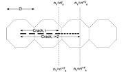
Figure 1. Schematic showing the position of n1 prior (nc) and after (ns) the unblocking of the crack tip plasticity

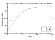
Figure 2a. The effect of surface roughness on the distribution of closure stress in a 2024-T351 SP component under mode I loading. The parameters used in the calculations are: ILF=5%,

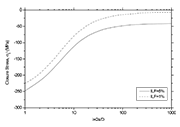
Figure 2b. The effect of ILF on the distribution of closure stress in a 2024-T351 SP component under mode I loading. The parameters used in the calculations are: Kt=1.25,

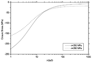
Figure 2c. The effect of the far-field stress on the distribution of closure stress in a 2024-T351 SP component under mode I loading. The parameters used are: Kt=1.25, ILF=1%,
Introduction
It is now clear that the performance of shot peening (SP) in terms of fatigue, depends on the balance between it¡¯s beneficial (compressive residual stress and work hardening) and detrimental effects (surface roughening) [1]. Hence, in order to achieve a favourable fatigue performance, the role of the above effects has to be analysed and understood. To achieve such undertaking it is essential to consider their interaction with other parameters such as the nature of the target material and the loading conditions.
This work brings together two micromechanical models; one for notch sensitivity [2] and for fatigue life [3]. The former assesses the effect of surface roughening, whilst the latter incorporates the residual stress distribution and work hardening on fatigue life calculations. Combination of the two models allows the determination of the residual stress distribution to meet specific improvements in fatigue life (improvement life factor, ILF). Using the ILF methodology, the effects of SP can be scrutinised against the stress level, the surface roughness and the ILF value.
Modelling the Surface Roughness
On shot peened surfaces, cracks are
likely to form at micro-notches (dents). Early studies from Smith [4] and
Tanaka [5] indicate that the propagation of cracks from notches depends on the
bluntness of the notch, given by (r is the notch
radius). Despite the numerous models published in the literature, an extended
citation is given in [6], most models fail to provide a relationship between
the geometry of the notch and the microstructure of the material. Such
relationship was successfully provided by Vallellano et al [2, 7]. According to
their work, the nominal stress in a notched member is given by,
(1)
where is the applied stress,
is the distribution of the nominal stress ahead of the notch
root as a function of the distance from the notch i, mapped as i=2a/D, and Zi
is the notch factor given by,
,
(2)
where i=1,3,5,¡
The parameters and
represent in a
dimensionless form the notch depth a and the notch half width b. The parameter
D represents the distance between two successive barriers. In the case where
grain boundaries are considered being the dominant barrier, D is regarded as
the grain diameter.
Li et al [8], proposed that the elastic stress concentration Kt introduced by multiple micro-notches in SP, is somehow lower than the one determined in the case of a single notch of similar depth and width. The above finding reflects the uniformity of the micro-notches on the surface. According to Li, the resulting Kt from SP is given by,
(3)
where the parameters Rt and S are respectively the mean of peak-to-valley heights and the mean spacing of adjacent peaks in the surface roughness profile. In the case of a semi-elliptical notch and a high degree of uniformity (SP coverage percentage of more than 100%), Eq.(3) can be written as,
(4)
At the beginning of this section it was pointed out that the bluntness of the notch can significantly affect the strain generated at the root of the notch and consequently the propagation rate of the crack. In light of that, Smith and Miller [4] proposed that Kt should be determined by,
(5)
where r is the notch root radius.
In the case of a semi-elliptical notch, the notch root radius can be
approximated by and thus Eq.(5) can
be rewritten as,
(6)
where g is the notch half width that considers the bluntness of the notch. By equating Eq.(6) with Eq.(4), the stress concentration due to multiple micro-notches can be expressed in terms of a single notch by,
(7)
Modelling the Fatigue Life in CSP components
In [3] it was proposed that the fatigue life of polycrystalline materials can be determined by,
(8)
where A2,
m2 are parameters from the Paris law of crack propagation, CTOD is
the crack tip opening displacement and ,
are limit values of n1 as defined in Fig. 1.
Figure 1. Schematic showing the position of n1 prior (nc) and after (ns) the unblocking of the crack tip plasticity.
In Eq.(8) the parameter and
represent
respectively, the position of the crack tip at the beginning and end of each
interval i of crack growth. These two parameters are calculated by,
(9)
where s2 is the flow resistance of the material and is the Kitagawa-Takahashi formula for a plain specimen,
(10)
with sFL denoting the fatigue limit of the plain material. In Equation 10 the parameter mi/m1 represents the effect of the grain orientation factor. More details can be found in [3, 9].
From Eq.(8) it is clear that the number of cycles required by the
crack to propagate an i number of half grains, depends solely on the parameter . For SP components, the parameter
has to be modified in
a way that it would take into account the roughening of the surface and the
crack closure stresses generated by the residual stresses,
(11)
where the parameter Zi is
taken by Equation 2. The Kitagawa-Takahashi formula for the case of SP,, is given by [3],
(12)
where . Hence, Equation 12 is rewritten as,
(13)
Introducing the Improvement Life Factor (ILF)
In order to increase the life consumed at each grain and consequently the overall life of the SP component, we make use of a predetermined ILF,
(14)
where the values of ILF are in percentage. Solution of Equation 14 in terms of CTOD yields,
(15)
In the case of a plain/unpeened material, Equation 15 is written as,
(16)
The fact that the value of CTOD at the position nc, where the crack tip plasticity is able to overcome the microstructural barrier, is identical for both the peened and the unpeened material (for the same loading conditions) allows Equations 15, 16 to be equated,
(17)
Simplification of Equation 17 gives,
(18)
From Equation 18, the
closure stress can be determined. It should be noted that due to the
complexity of Equation 18, a computational solution is advised. Fig. 2 shows
the calculated crack closure,
, for several conditions of loading and treatment.
Discussion and Conclusions
In this work the effects of SP are analysed and modelled according to their effects on fatigue damage. Surface roughness is modelled in a way that would increase the far-field stress. Hence, the component appears having an amplified capacity of initiating and propagating short fatigue cracks. Compressive residual stresses translated as closure stresses are regarded as one of the beneficial effect of SP. Residual stresses tend to reduce the application of the far-field stress by introducing a closure stress on the crack flanks. Thus, the propagation of the crack is expected to be somewhat reduced compared to the unpeened condition. Finally, strain hardening is expected to reduce the propagation of short fatigue cracks by increasing the ability of the material to localised straining (crack tip plastic zone).
The introduction of a predetermine improvement in terms of fatigue life (ILF) has been achieved by introducing the ILF into the number of fatigue cycles consumed in every grain. The above approach allows the mathematical modelling of the conflict between the beneficial and detrimental SP effects. At first, the analysis reveals that the magnitude of the closure stresses should always attain a maximum at the surface. Such distribution minimises the premature initiation of a ¡°visible¡± fatigue crack. Secondly, the depth distribution should be able to follow the stress gradient generated by the surface roughness. Further analysis allows to scrutinise against parameters like the far-field stress level, the ILF and the surface roughness. From Figure 2, the effect of the above parameter is classified in the following order, starting from the most decisive: a) Surface Roughness. The analysis reveals that a 12% increase, measured in terms of Kt, in the surface roughness requires a 47% increase in the closure stress magnitude to allow a 5% increase in the per grain life. Additionally, a higher Kt would require deeper closure stresses; b) Far-Field Stress Level. In principle high far-field stress levels require high magnitude and deeper closure stresses. This comes as a verification to the fact, published extensively in the literature, that SP will have a minimum effect, or in some cases a detrimental effect, on the low cycle fatigue region; and c) ILF. The analysis reveals that SP components are not so sensitive to different ILF values. The above finding is in accordance to many experimental data where short cracks were found to propagate almost irrespective of the crack closure stress levels.
It should be noted that due to the fact that the methodology is expressed in terms of crack length, it can be easily adjusted to incorporate relaxation profiles of residual stress and strain hardening.
References
[1] S. Curtis, E. R. de los Rios, C. A. Rodopoulos and A. Levers, Inter. J. of Fatigue, 25 (2003), 59-66.
[2] C. Vallellano, A. Navarro and J. Dom¨ªnguez, Fatigue Fracture Engineering Materials Structures, 2000, 23, 113-121.
[3] E. R. de los Rios, M. Trull and A. Levers, Fatigue Fracture Engineering Materials Structures, 2000, 23, 709-716.
[4] R. A. Smith and K. J. Miller, Inter. J. Mech. Sci., 1978, 20, 201-206.
[5] K. Tanaka, Inter. J. Fract., 1983, 22, R39-R45.
[6] S. Suresh, Fatigue of Materials, Cambridge University Press, 1991.
[7] C. Vallellano, A. Navarro and J. Dom¨ªnguez, Fatigue Fracture Engineering Materials Structures, 2000, 23, 123-128.
[8] J. K. Li, M. Yao, D. Wang., R. Wang, Fatigue Fracture Engineering Materials Structures, 1999, 15(12), 1271 ¨C 1279.
[9] E. R. de los Rios and A. Navarro, (1990) Philosophical Magazine 1990, 61, 435-449.
E-mail: josesolis@infinitum.com.mx
Afiliation:
SEP-DGEST-IT de Tlalnepantla
UMSH-IIM
UP-Pachuca


