E-Archive
Good Vibrations
in Vol. 17 - July Issue - Year 2016
Centrifugal Disk Machines - Surface Finishing At "Turbo" Speeds
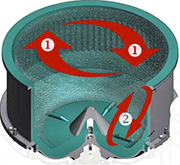
Photo 1: Schematic of centrifugal disk-finishing machine
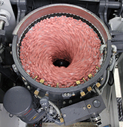
Photo 2: Glimpse into a running machine
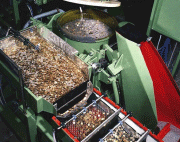
Photo 3: Coin blank finishing with a centrifugal disk-finishing machine
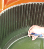
Photo 4: Manual measurement of the gap size with a feeler gauge
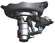
Photo 5: High precision double-acting hydraulic cylinder with built-in position sensor for automatic setting of the gap size
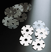
Photo 6: The new gap control system allows the safe processing of very thin parts (< 0.5 mm) without ever risking a machine crash
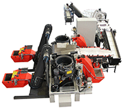
Photo 7: The new gap control system facilitates fully automatic operation with no operator intervention for high process safety and increased productivity
All mass finishing processes have one thing in common, namely the typical "relative" movement between the work pieces and the processing media. Of course, the most ubiquitous mass finishing systems are still vibratory machines, where the required energy is induced by vibration. More recently, special technologies like drag, plunge and surf finishing have become very popular for creating perfect surface finishes on high value components like orthopedic implants, turbine blades, etc., which must not touch each other during the finishing process. However, because of its exceptional productivity and high degree of automation centrifugal disk finishing has become the preferred method for finishing high volumes of mass produced small to midsize components.
Centrifugal disk finishing started with a potato-peeling machine
Like many other technological breakthroughs, the development of high energy centrifugal disk surface finishing was somewhat accidental: For many years food processing companies had used machines with a stationary cylindrical work bowl and a rotating disk in the bottom for peeling potatoes. In the early 1970's, it was discovered that the same functional principle could also be used for deburring small metal parts. The centrifugal force of the rotating disk forces the mixture of media and work pieces up the wall of the stationary work bowl. Once its kinetic energy is exhausted, the work piece/media mixture collapses back to the rotating disk, where it is accelerated again (photos 1 & 2). Over the years, centrifugal disk finishing has evolved into a sophisticated surface finishing technology. Because of its many operational advantages, it has become the preferred finishing method, whenever mass-produced work pieces must be treated in an automated manufacturing environment.
10 times higher productivity than vibratory finishing equipment
The most striking feature of centrifugal disk finishing is the fact that it is about 10 times more productive than vibratory systems. In other words, if a deburring process takes one hour in a vibrator, the same process can be run in a disk machine in around 6 minutes.
And, since the work bowl is always completely unloaded after completion of the finishing process, disk machines also guarantee absolute "batch integrity"! Different work pieces will never get mixed up. This is absolutely essential for any manufacturing operation, where the finished parts go directly to an automated assembly operation.
From aggressive deburring to gentle surface smoothing & polishing
Another feature of disk-finishing systems is the possibility to "flood" the work bowl with process water. Since water cushions the impact between media and work pieces, the overall process intensity can be varied from very aggressive to extremely gentle by simply running the process with a surplus of water in the work bowl. If a machine is equipped with a PLC the water level can be adjusted during the actual process. For example, this allows running the machine very aggressively in the initial process phase for effective deburring and edge radiusing and then, by adding water, transitioning to gentle surface smoothing and polishing. It is not surprising that centrifugal disk finishing is the preferred finishing method in the mint industry, where aggressive descaling and subsequent polishing of the coin blanks can be perfectly handled in one single process (Photo 3).
Protection of the seal gap - a constant challenge
Of course, centrifugal disk-finishing machines have one weak spot: The gap between the rotating disk and stationary work bowl is the most vulnerable area in any centrifugal disk machine. During the finishing process, small media and thin work pieces can creep into this gap and cause a machine to crash. Or the gap can become too small "fusing" the disk with the work bowl resulting in significant and costly damage to the machine. That is why proper setting and maintenance of an adequate gap size is essential for many centrifugal disk-finishing processes.
The problem is compounded by the fact that disk and work bowl are protected against premature wear with a polyurethane lining, which expands and contracts with increasing and decreasing temperatures respectively. A perfectly adjusted gap size can be easily reduced to zero with increasing operating temperatures due to the expanding polyurethane lining, which can cause a serious machine failure.
To date, the machine users have been coping with this problem by frequently measuring the gap by hand with a feeler gauge and re-adjusting its size by manually or hydraulically raising or lowering the rotating disk (photo 4). Some systems went one step further by automatically adjusting the gap size to a preset value after each processing cycle. While this represented significant progress, it still posed the risk of a machine failure, if for example, due to an interruption of the water supply or the process water becoming too hot, the operating temperature increased drastically during the process.
"On the fly" gap adjustment for treating extremely thin parts
One supplier of centrifugal disk systems has now introduced a gap control system that not only monitors the temperature in the gap area during the process but also continuously adjusts the gap size "on the fly" as dictated by increasing or decreasing operating temperatures.
This became possible by establishing empirical reference parameters with regard to the temperature-related changes of the gap size and storing these parameters in the equipment controls. As soon as the temperature in the gap area changes, the PLC sends instructions to an extremely precise double-acting hydraulic cylinder with built-in position sensor to widen or narrow the gap (photo 5). In case of extreme temperature increases, the PLC turns off the complete disk-finishing system.
Since this new control system - for which a patent was filed - continuously monitors and adjusts the gap size throughout the entire finishing process, very tight gap size settings are now possible allowing the treatment of thin gauge parts with a thickness of < 0.5 mm without ever risking the gap becoming too tight and causing a failure.
Easy automation
With the new control system, manual measuring and adjustment of the gap size is no longer required, and the risk of a machine crash during the finishing cycle due to changing operating conditions has been completely eliminated. This allows running fully automated finishing processes without any operator intervention and machine downtimes. The new system increases not only overall process safety but also allows full exploitation of high productivity of centrifugal disk finishing systems.
Good Vibrations
by Eugen Holzknecht
Contributing Editor MFN and
Rösler Oberflächentechnik GmbH
E-mail: holzknecht.usa@gmail.com


