E-Archive
Articles
in Vol. 19 - September Issue - Year 2018
Introduction Of Enhanced Compressive Residual Stress Profiles In Aerospace Components Using Combined Mechanical Surface Treatments

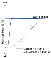
Figure 1. Approximation of Residual Stress profiles for Surface and subsurface treatment

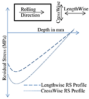
Figure 2. Depiction of lengthwise and crosswise stress profiles for DCR

Figure 3: Normalized residual stress profiles for both individual processes and the combination process
Abstract: Mechanical surface treatments such as Shot Peening (SP) and Deep Cold Rolling (DCR) are being used to introduce Compressive Residual Stress (CRS) at the surface and subsurface layers of aerospace components respectively. This paper investigates the feasibility of a combined introduction of both the surface and sub-surface compressive residual stress on Ti6Al4V material through a successive application of the two aforementioned processes, one after the other. CRS profiles between individual processes were compared to that of combination of processes to validate the feasibility. It was found that shot peening introduces surface compressive residual stress into the already deep cold-rolled sample, resulting in both surface and sub-surface compressive residual stresses in the material. However the drawback of such a combination would be the increased surface roughness after shot peening of a deep cold-rolled sample that can be critical especially in compressor components. Hence, a new technology, Vibro-Peening (VP) may be used as an alternative to SP to introduce surface stress at reduced roughness.
1. Introduction
Crack initiation and propagation is one of the key challenges faced in aerospace industry [1]. High levels of vibrational stresses, frettage fatigue and Foreign Object Damage (FOD) are the main sources of crack initiation in an aerospace component. Introduction of Compressive Residual Stresses (CRS) into the material delays the mechanisms leading to crack initiation and crack propagation thereby improving the fatigue life of the component [2].
Shot Peening (SP) is one of the widely used cold working techniques to induce residual stresses on the component surface [3]. This process uses spherical balls called as shot or projectile to impact the part surface at high velocity, creating plastic deformation through indents on the surface. A larger region of compressive residual stress in the surface zone is introduced as the thin plastic deformation near the surface is resisted (compressed) by the bulk elastic material [4].The key variables in shot peening are the density, size and shape, hardness of the shot, air pressure used for peening, nozzle type, shot velocity, angle of impingement and hardness, geometry and preload of the component.
Deep Cold Rolling (DCR) is a mechanical surface treatment technique that uses a hydrostatically controlled ball or roller tool, to impart a contact stress larger than the yield stress of the component, leading to plastic deformation and a three-dimensional Hertzian stress pattern around the point of contact [5]. Although DCR has its roots in roller burnishing and shares common benefits, the main aim of DCR is to induce plastic deformation which results in compressive residual stress in the surface and sub-surface region of the component, while roller burnishing is mainly used to attain a high quality mirror-like finish on the surface of the component [6].
Figure 1 shows the typical stress distribution through the depth of a component for a surface and a subsurface process. DCR generally introduces sub surface stress of significant compressive level up to a depth of 500 µm to 1 mm, while SP introduces compressive surface stress below 200 µm. This paper investigates the feasibility of combining surface and sub-surface stresses.
One of the characteristics of DCR is that, this process induces directional stresses unlike SP which introduces isotropic stresses. In DCR, stresses that are perpendicular to the rolling direction (crosswise) are higher than the stresses along the direction of rolling (lengthwise). Figure 2 illustrates the crosswise (CW) and lengthwise (LW) direction with respect to the rolling direction for DCR. By combining DCR with SP, we intend to investigate the possibility of decreasing the gap between lengthwise and crosswise stresses as well.
2. Measurements and methodology
Three flat coupons (30x30x20 mm3) of Ti6Al4V (ASTM Grade 5) material were used in this study. The first coupon was deep cold-rolled using a 12.6 mm ball, the second was shot-peened using 200% coverage using 8A intensity and the third one had DCR followed by SP. The tests were repeated for two sets of coupon for repeatability check and the average of the two sets was taken. The residual stress measurements were conducted by Centre Hole Drilling (CHD) with Vishay Precision Group type EA-06-062RE-120 gauge using the orbital hole drilling procedure. Stresses obtained had a length wise and crosswise component since DCR is a directional technique.
3. Results and discussion
The compressive residual stress profiles are compared in Figure 3 between SP, DCR and DCR + SP based on the following parameters: stresses at the surface, peak residual stress and the depth at which peak stress occurs and the transition depth from compressive to tensile residual stresses. The residual stress profiles have been normalized against the maximum compressive residual stress value measured across all five residual stress depth profiles.
It can be observed that the residual stress depth profile from SP is identical in both directions. However, for the near surface region, up to a depth of about 500 µm, DCR has different residual stress profiles in the lengthwise and crosswise directions as shown in Figure 3. This is due to the mechanism of the DCR process in which the burnishing ball element generates a bow wave in advance of the rolling direction. As a result of this bow wave, material is pushed perpendicular to the rolling direction. More material is pushed perpendicularly to the rolling direction relative to that parallel to the rolling direction. This was reported by Balland et al. [7] through the use of finite element simulation modelling of a single path of the burnishing process. In addition, Lim et al. [8] demonstrated that the net movement of material in the surface region led directly to larger plastic strains and hence more compressive residual stress, through the finite element process modelling of a full DCR treatment.
It can be seen from Figure 3 that the effect of the combined process led to a significant improvement of the compressive surface RS in the lengthwise direction after SP. However, the effect on the crosswise stresses was insignificant as no improvement was observed after SP. This behaviour could be attributed to the fact that the high levels of near-surface stress after DCR had already led to saturation of induced stresses in the crosswise direction, and the plastic deformation in the component was unable to gain the benefits from SP. Overall, this also means that SP post DCR reduces the deviation between crosswise and lengthwise stresses at the surface, thereby reducing the directionality of DCR.
4. Discussions and recommendations
Based on the experimental investigations, it can be concluded that combination of SP with DCR could introduce the surface stress into Ti6Al4V, thus producing both surface and sub-surface RS into the specimen. However, the introduction of SP after DCR increases the roughness of the surface to about 1.5 µm, negating the surface smoothness produced by DCR (Ra ~ 0.3 µm). This might create minor aerodynamic issues especially if used in compressor components. In order to address this limitation, a new method called Vibro-Peening (VP) is proposed as an alternative to SP [9].
Vibro-Peening (VP) is a process that involves both impact and sliding of media on to a component. With the impact of media on the component being comparable to that of shot peening, the near-surface stresses from VP can be compared to that of SP. The additional sliding of the media on to the surface helps in reducing the surface roughness compared to SP. Hence instead of SP, VP can be combined with DCR to produce both surface and sub-surface CRS into the material and also results in smoother surface than SP. Feldmann et al. [9] compared the roughness between SP and VP in 6 different specimens. It has been proved that the SP surface is rougher than the pre-treated surface while the VP surface has a better finish compared to the pre-treated surface.
In addition to the surface roughness improvement, there are more advantages of using VP as compared to SP, one being the fact that the tool path of SP process consumes a long processing time in order to complete the peening treatment, especially for complex geometry, whereas VP is expected to be faster for larger components. VP can hence be developed for its potential in achieving necessary compressive residual stresses and lower surface roughness as a single-step process. Its success would result in considerable reduction of both cost and process time.
5. Conclusion
A feasibility study was performed for combining sub-surface (DCR) and surface (SP) manufacturing techniques to get both sub-surface and surface stresses on a Ti6Al4V flat coupon. The results showed that the lengthwise surface stress induced by DCR was improved by combining it with SP, thereby producing surface and sub-surface RS and also making the DCR technique more directional. In addition, VP is suggested as an alternative to SP to improve the surface finish.
Acknowledgements
This work was partially conducted within the Rolls-Royce@NTU Corporate Lab with support from the National Research Foundation (NRF) Singapore under the Corp Lab@University Scheme. Andre Lim wishes to acknowledge the support of the Singapore Economic Development Board (EDB) Industrial Post Graduate Programme (IPP).
References
[1] Jata K V, Roy A and Parthasarathy T A 2009 Encyclopedia of Structural Health Monitoring, (Hoboken: John Wiley & Sons, Ltd)
[2] Altenberger I 2006 Shot Peening, ed L Wagner (Weinheim: Wiley-VCH Verlag GmbH & Co. KGaA) pp 419-34
[3] Schulze V 2006 Modern mechanical surface treatment: states, stability, effects (Weinheim: John Wiley & Sons)
[4] Verpoort C and Gerdes C 1989 Metal Behaviour & Surface Engineering, , ed S Curioni, et al. (Lincoln: IITT International) pp 97-155
[5] Altenberger I 2005 Deep rolling—the past, the present and the future. In: Proc. 9th Int. Conf. Shot Peening, ed V Schulze and A Niku-Lari (Paris: IITT-International) pp 144-55
[6] Majzoobi G, Azadikhah K and Nemati J 2009 The effects of deep rolling and shot peening on fretting fatigue resistance of Aluminum-7075-T6 Mater. Sci. Eng. A-Struct. Mater. Prop. Microstruct. Process. 516 235-47
[7] Balland P, Tabourot L, Degre F and Moreau V 2013 Mechanics of the burnishing process Precis. Eng.-J. Int. Soc. Precis. Eng. Nanotechnol. 37 129-34
[8] Lim A, Castagne S and Wong C C 2016 Effect of Deep Cold Rolling on Residual Stress Distributions Between the Treated and Untreated Regions on Ti–6Al–4V Alloy J. Manuf. Sci. Eng.-Trans. ASME 138 111005
[9] Feldmann G, Wong C C, Wei W and Haubold T 2014 Application of Vibropeening on Aero–Engine Component Procedia CIRP 13 423-8
*This paper was published by IOP Publishing Ltd in the IOP Conference Series: Materials Science and Engineering, Volume 157, Number 1
For Information:
Abhay Gopinath1,2
Andre Lim1,2, Balasubramanian Nagarajan3 Chow Cher Wong1, Rajarshi Maiti1,2
Sylvie Castagne2,*
1 Rolls-Royce Singapore, Advanced Technology Centre, 6 Seletar Aerospace Crescent, Singapore 797575
2 School of Mechanical and Aerospace Engineering, Nanyang Technological University, 50 Nanyang Avenue, Singapore 639798
3 Rolls-Royce@NTU Corporate Laboratory, c/o School of Mechanical & Aerospace Engineering, 50 Nanyang Avenue, Nanyang Technological University, Singapore 639798
*scastagne@ntu.edu.sg


