Shot peening is a controlled cold working process that improves fatigue performance by introducing compressive residual stress into the near-surface region of metallic components. The process involves accelerating small spherical media toward a component surface at high velocity, producing localized plastic deformation at each impact site. The cumulative effect of repeated impacts creates a compressive stress layer that suppresses fatigue crack initiation and slows crack propagation. Because fatigue cracks preferentially initiate at free surfaces subjected to tensile stress, the introduction of compressive residual stress significantly enhances fatigue life and structural durability. However, the process must be applied selectively in many applications to avoid degrading precision surfaces, altering dimensional tolerances, or introducing unintended distortion in thin sections.
When shot peening components, it is common practice to mask localized regions where peening roughness and additional residual stress are not desirable. Precision-machined features such as bearing races, sealing lands, interference-fit surfaces, and fatigue test gauge sections frequently require protection to prevent plastic deformation and unwanted surface modification.
During fatigue and crack growth testing, specimens are typically clamped within hydraulic wedge grips that contain serrated or diamond-patterned faces. These grips prevent slippage during high cyclic loading but can introduce fretting damage and localized surface distress. To mitigate this, grip regions are often shot peened to introduce beneficial compressive residual stress. However, maintaining an as-machined surface finish within the gauge section is essential to preserving test validity and ensuring repeatable mechanical performance. Masking is therefore routinely applied during shot peening operations, and acceptance is commonly based on a qualitative "no-observable-dimples" criterion where surface finish and geometry must remain tightly controlled.
Although published specifications such as AMS 2430, AMS 2432, and BAC 5730 provide some limited quantitative guidance regarding masking material thickness and performance thresholds, little formal guidance exists regarding appropriate masking thickness, number of layers, or performance limits at varying peening intensities and coverage levels despite the widespread use of tape masking.
In practice, masking acceptance is commonly based on visual inspection for dimples, often conducted with the unaided eye and without defined magnification or lighting requirements. However, the absence of visible dimples does not necessarily confirm that residual stress has not been altered beneath the surface. Plastic deformation energy may be partially transmitted through masking materials without producing clearly visible indentations. A study was therefore designed to quantitatively evaluate the effectiveness of common tape masking materials under varying peening conditions using X-ray diffraction residual stress measurements to evaluate whether compressive residual stress may still be introduced beneath masked regions even when no visible surface dimples are observed.
Residual stress mapping using X-ray diffraction was performed on coupons masked with varying tape thicknesses and subjected to multiple peening intensities and coverage levels representative of aerospace processing conditions.
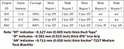
Three commercially available masking tapes were evaluated in this study: Duct Tape® with a nominal thickness of approximately 0.127 mm (0.005 inch), IPG® Iron Grip with a thickness of approximately 0.381 mm (0.015 inch), and Anchor® T227 Medium Tack Blastlite with a thickness of approximately 0.711 mm (0.028 inch). These materials represent products commonly used in masking operations during low to moderate–volume shot peening applications.
Test coupons were machined from 7050-T7451 aluminum plate approximately 25.4 mm thick and finished to rectangular geometry to minimize distortion during peening. Masked regions were applied using one, two, or three layers of thin tape, as well as thicker configurations using the alternative materials (see Table 1). Three peening conditions were applied: an 11A Almen intensity with 200 percent coverage, representing typical aerospace aluminum processing; a 10C intensity with 200 percent coverage, representing a higher severity condition; and a 10C intensity with 400 percent coverage, representing an aggressive, high-energy application.
Residual stress measurements were obtained to quantify the effectiveness of masking configurations. Surface residual stresses were measured before and after peening using X-ray diffraction in accordance with ASTM standards. Baseline measurements in the as-machined condition revealed low-magnitude compressive residual stresses relative to the yield strength of 7050-T7451 aluminum. These machining-induced stresses were modest and served as the reference condition for evaluating stress changes induced by shot peening.
Measurements were collected on a uniform grid across masked and unmasked regions to generate residual stress maps. A 2 mm by 2 mm incident beam aperture defined the irradiated area for each measurement (see Figure 1).
Under moderate peening intensity (11A with 200 percent coverage), unmasked regions exhibited uniform compressive residual stress consistent with typical aluminum shot peening behavior. Masked regions protected by two or three layers of thin tape showed negligible residual stress change relative to baseline measurements. One layer of thin tape allowed minor surface dimpling but did not produce statistically significant stress modification beyond experimental uncertainty. These results indicate that moderate peening intensity can be effectively mitigated using relatively thin masking configurations when sufficient layering is applied.
At higher peening intensity (10C with 200 percent coverage), masking performance was strongly dependent on thickness. One layer of thin tape failed to prevent dimpling and allowed substantial compressive residual stress transfer into the masked region. Two layers reduced but did not eliminate measurable stress change. Three layers were required to prevent visible dimpling and minimize residual stress modification to levels approaching baseline. This demonstrates that masking requirements increase nonlinearly with peening intensity.
When coverage was increased to 400 percent at 10C intensity, even three layers of thin tape were insufficient to fully prevent surface effects. Thicker masking materials prevented visible dimples but still allowed small measurable compressive residual stresses to develop beneath the masked surface. Although these stresses were small relative to the material yield strength, they were consistently detectable using X-ray diffraction measurement. This finding suggests that complete elimination of stress transfer may be difficult at high intensity and high coverage conditions.
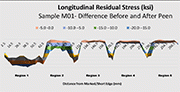
The difference in residual stress between shot-peened and baseline conditions for each coupon are plotted in Figure 2.
Using the data plotted in Figure 2, the average difference in residual stress for each region was calculated and tabulated in Table 2.
The absence of tensile transition stress indicates that masking does not introduce detrimental tensile concentrations under the processing parameters evaluated. However, partial compressive stress transfer was observed even in the absence of visible dimples, confirming that the qualitative inspection criterion alone is insufficient to guarantee an unchanged stress state.
Residual stress vs. depth profiles were subsequently collected on Coupon H02 after shot peening by incremental electropolishing to access deeper layers so as to determine how the near-surface material (up to ~1 mm (or 0.040 inch) deep) responded to the shot peening process with the different masking configurations applied. Residual stresses were determined in the approximate center of the unmasked region, as well as in Mask Regions 1, 2, and 3. An additional residual stress vs. depth profile was also collected on a coupon in the "as machined" condition prior to peening. The condition of Coupon H02 after electropolishing the final depths can be seen in Figure 3, and the residual stress vs. depth profiles collected are plotted in Figure 4.
Results found in the unmasked region provide a representation of the residual stress typically expected using a peening Almen intensity of 10C using 330 shot media with 200% coverage on Al 7050-T745. The residual stress vs. depth profile from Mask Region 1 using one layer of ~0.127 mm (0.005 inch) thick Duct Tape® represents a reduced, but still significant, effect of the shot peening applied. The effective depth and maximum compressive residual stress achieved due to peening in this region were significantly reduced as compared to the unmasked region; however, it is interesting to note that the surface residual stress in this case is more compressive than that in the unmasked region. This is because the effective peening intensity was reduced by the tape which resulted in less damage and surface roughness. The effect was persistent in Coupon H02 in Mask Region 1. Moreover, a similar effect was seen in Mask Region 1 on Coupon M01. The residual stress vs. depth profiles for Mask Regions 2 and 3 (with two layers and three layers of ~0.127 mm (0.005 inch) thick Duct Tape® respectively) show a low-magnitude compressive residual stress field with increasing depth, crossing into tension at ~0.076 mm to 0.127 mm (~0.003 to 0.005 inch) deep. The difference between these profiles and the one found in the "as machined" condition is small but clearly observable.
Subsurface residual stress profiles confirmed that insufficient masking thickness allows partial transmission of peening energy into underlying material. In some cases, compressive surface stress beneath a single thin layer exceeded that of adjacent unmasked regions, likely due to reduced surface roughness while still transmitting impact energy. Increasing masking thickness reduced both the magnitude and effective depth of compressive stress transfer, demonstrating that masking acts primarily as an energy attenuation medium rather than a complete barrier.
The commonly used no-observable-dimples acceptance criterion is generally effective at moderate intensity but does not fully guarantee the absence of residual stress modification at higher intensities or coverage levels. Measurable compressive residual stress transfer may occur even when visible dimples are absent. For this reason, development of quantitative masking specifications, minimum thickness guidelines tied to peening parameters, and standardized inspection criteria would improve consistency and reliability in aerospace shot peening operations.
Jim Harrison, CWST (retired), E-mail: jharrison@protoxrd.com
James Pineault, Proto Mfg., E-mail: xrdlab@protoxrd.com
Tom Mills, APES, E-mail: tmills@apesolutions.com
Scott Carlson, LMCO, E-mail: scott.carlson@lmco.com
For Information:
Proto Mfg. Inc.
12350 Universal Drive, Taylor, Michigan
USA, 48180-4070
Tel. +1.734.946-0974
www.protoxrd.com




 BACK
BACK